
User Manual


D03Rev2.3
11
DMT proprietary & confidential: product information is subject to change without notice.
Domintech Co., Ltd. Tel: +886-2-2290-1288 Fax: +886-2-2290-1266 http://www.domintech.com.tw
Source Configure”, "Freefall Interrupt Enable" and "Freefall Threshold" for proper register setup.
High-G Interrupt Flag
HGInt (0Ch:bit6) is the high-G interrupt flag. The high-G interrupt flag serves the same purpose
and manner as the configured INTx pin. This flag can be read via the SPI/I2C digital interface, and
therefore is an alternative to the INTx pin if end users have GPIO constraint. See “INT1 and INT2
Source Configure” and “High-G Detection” for proper register setup.
X-axis High-G Flag
XHGP(0Ch:bit5) and XHGN(0Ch:bit4) is the flag for the high-G detection along the X-axis positive
and negative direction respectively. XHGP is set when the X-axis acceleration exceeds the positive
value of the high-G threshold. Likewise XHGN is set when the X-axis acceleration falls beyond the
negative value of the high-G threshold. Please refer to “High-G Detection” for proper register setup.
Y-axis High-G Flag
YHGP(0Ch:bit3) and YHGN(0Ch:bit2) is the flag for the high-G detection along the Y-axis positive
and negative direction respectively. YHGP is set when the Y-axis acceleration exceeds the positive
value of the high-G threshold. Likewise YHGN is set when the Y-axis acceleration falls beyond the
negative value of the high-G threshold. Please refer to “High-G Detection” for proper register setup.
Z-axis High-G Flag
ZHGP(0Ch:bit1) and ZHGN(0Ch:bit0) is the flag for the high-G detection along the Z-axis positive
and negative direction respectively. ZHGP is set when the Z-axis acceleration exceeds the positive
value of the high-G threshold. Likewise ZHGN is set when the Z-axis acceleration falls beyond the
negative value of the high-G threshold. Please refer to “High-G Detection” for proper register setup.
Click Interrupt Flag
CLInt (0Dh:bit6) is the click interrupt flag. The click interrupt flag serves the same purpose and
manner as the configured INTx pin. This flag can be read via the SPI/I2C digital interface, and
therefore is an alternative to the INTx pin if end users have GPIO constraint. See “INT1 and INT2
Source Configure”, "Click Interrupt Enable" and "Click Threshold" for proper register setup.
X-axis Click Flag
XCLP (0Dh:bit5) and XCLN (0Dh:bit4) are X-axis positive and negative direction click flag. The flag
will be latched to 1 upon detecting click event along X-axis when the configured INT× pin is latched to
logic-1. The X-axis click event is to check double-crossing some click threshold. Depending on the
double-crossing direction, positive or negative flag is set respectively. The click event is fired at the
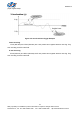
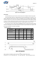
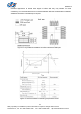
second crossing. For example, when the X-axis click enable is set, i.e. CLXEn (09h:bit2) = 1, with default
threshold value 2.0g, i.e. Clickth[3:0] (0Bh:bit3~0) = 08h, Figure 5 shows a scenario that the X
acceleration first double-cross the positive threshold 2.0g and then secondly double-cross the negative
threshold -2.0g. The first double-cross will trigger positive direction click (flag XCLP set to 1) at the
second cross. The latter double-cross will trigger negative direction click (flag XCLN set to 1) at the
second cross. See “INT1 and INT2 Source Configure”, "Click Interrupt Enable" and "Click Threshold" for