
User Manual

D03Rev2.3
10
DMT proprietary & confidential: product information is subject to change without notice.
Domintech Co., Ltd. Tel: +886-2-2290-1288 Fax: +886-2-2290-1266 http://www.domintech.com.tw
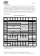
Click Interrupt Enable
CLXEn, CLYEn, CLZEn (09h:bit2, 1, 0) are the X-, Y-, and Z-axis click interrupt enable control bits
respectively. If the respective click interrupt enable bit is set to 1, click monitoring is enabled for the
respective axis. DMARD03 will check closely if the respective axis acceleration value double crosses
some click threshold. In such case a click event is detected on the way of second cross. On detection
the configured INT× pin will be latched to logic-1. The click interrupt flag (CLInt, 0Dh:bit6) serves the
same purpose and manner as the INTx pin. This flag can be read via the SPI/I2C digital interface, and
therefore is an alternative to the INTx pin if end users have GPIO constraint. Respective click direction
flags (XCLP, XCLN, YCLP, YCLN, ZCLP, ZCLN, 0Dh:bit5~0) will also be set to 1 depending on
detected axis and direction. The latch will be automatically cleared after the click flag register (0Dh) is
read. See "Interrupt Status Registers" for details. For INT× configuration, see “INT1 and INT2 Source
Configure”. User can set respective click threshold, see "Click Threshold" for details.
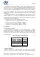
High-G Threshold
HGth[3:0] (0Ah:bit7~4) is the 4-bit high-G threshold control register with 250mg per code. The
effective setting range is from 0Ch (3.0g) to 01h (250mg). The default value is 08h (2.0g). See "High-G
Interrupt Enable" for high-G detection enable control.
Freefall Threshold
FFth[3:0] (0Ah:bit3~0) is the 4-bit freefall threshold control register with 62.5mg per code. The
effective setting range is from 0Fh (937.5mg) to 01h (62.5mg). The default value is 08h (500mg). See
"Freefall Interrupt Enable" for freefall detection enable control.
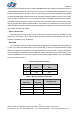
Click Threshold
Clickth[3:0] (0Bh: bit3~0) is the 4-bit click threshold control register with 250mg per code. The
effective setting range is from 0Ch (3.0g) to 01h (250mg). The default value is 08h (2.0g). The
threshold will be checked against double-cross for click event when the click interrupt enable is set,
see "Click Interrupt Enable" for proper register setup. Appropriate flag will be set to 1 upon detecting
click event when the INT pin is latched to logic-1, see "Interrupt Status Registers" for details.
Interrupt Status Registers
0Ch and 0Dh serve as the interrupt status registers. When relevant events trigger interrupts,
configured INT× pin and appropriate interrupt status bits will be set. For a non-latched interrupt, the
interrupt status register can serve as a replica of configured INT×, and accessed from typical digital
interface instead of dedicated GPIO. For a latched interrupt, more detailed information is kept in the
interrupt status registers for users to further distinguish interrupt sources. The latch will be
automatically cleared after appropriate interrupt status register is read.
Freefall Interrupt Flag
FFInt (0Ch:bit7) is the freefall interrupt flag. The freefall interrupt flag serves the same purpose
and manner as the configured INTx pin. This flag can be read via the SPI/I2C digital interface, and
therefore is an alternative to the INTx pin if end users have GPIO constraint. See “INT1 and INT2