
User Manual


VS1003
10 VS1003 REGISTERS
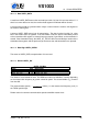
Example UART Speeds, f
m
= 26MHz
Comm. Speed [bps] UART_DIV_D1 UART_DIV_D2
4800 85 63
9600 42 63
14400 42 42
19200 51 26
28800 42 21
38400 25 26
57600 1 226
115200 0 226
10.11.6 Interrupts and Operation
Transmitter operates as follows: After an 8-bit word is written to the transmit data register it will
be transmitted instantly if the transmitter is not busy transmitting the previous byte. When the
transmission begins a TX_INTR interrupt will be sent. Status bit [1] informs the transmitter data
register empty (or full state) and bit [0] informs the transmitter (shift register) empty state. A
new word must not be written to transmitter data register if it is not empty (bit [1] = ’0’). The
transmitter data register will be empty as soon as it is shifted to transmitter and the transmission
is begun. It is safe to write a new word to transmitter data register every time a transmit interrupt
is generated.
Receiver operates as follows: It samples the RX signal line and if it detects a high to low
transition, a start bit is found. After this it samples each 8 bit at the middle of the bit time (using
a constant timer), and fills the receiver (shift register) LSB first. Finally if a stop bit (logic high)
is detected the data in the receiver is moved to the reveive data register and the RX_INTR
interrupt is sent and a status bit[2] (receive data register full) is set, and status bit[2] old state is
copied to bit[3] (receive data overrun). After that the receiver returns to idle state to wait for a
new start bit. Status bit[2] is zeroed when the receiver data register is read.
RS232 communication speed is set using two clock dividers. The base clock is the processor
master clock. Bits 15-8 in these registers are for first divider and bits 7-0 for second divider. RX
sample frequency is the clock frequency that is input for the second divider.
Version: 1.08, 2014-12-19 53