
User Manual


VS1003
10 VS1003 REGISTERS
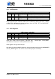
10.8 Interrupt Registers
Interrupt registers, prefix INT_
Reg Type Reset Abbrev[bits] Description
0xC01A rw 0 ENABLE[7:0] Interrupt enable.
0xC01B w 0 GLOB_DIS[-] Write to add to interrupt counter.
0xC01C w 0 GLOB_ENA[-] Write to subtract from interript counter.
0xC01D rw 0 COUNTER[4:0] Interrupt counter.
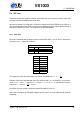
INT_ENABLE controls the interrupts. The control bits are as follows:
INT_ENABLE bits
Name Bits Description
INT_EN_TIM1 7 Enable Timer 1 interrupt.
INT_EN_TIM0 6 Enable Timer 0 interrupt.
INT_EN_RX 5 Enable UART RX interrupt.
INT_EN_TX 4 Enable UART TX interrupt.
INT_EN_MODU 3 Enable AD modulator interrupt.
INT_EN_SDI 2 Enable Data interrupt.
INT_EN_SCI 1 Enable SCI interrupt.
INT_EN_DAC 0 Enable DAC interrupt.
Note: It may take upto 6 clock cycles before changing INT_ENABLE has any effect.
Writing any value to INT_GLOB_DIS adds one to the interrupt counter INT_COUNTER and
effectively disables all interrupts. It may take upto 6 clock cycles before writing to this register
has any effect.
Writing any value to INT_GLOB_ENA subtracts one from the interrupt counter (unless INT_COUNTER
already was 0). If the interrupt counter becomes zero, interrupts selected with INT_ENABLE
are restored. An interrupt routine should always write to this register as the last thing it does,
because interrupts automatically add one to the interrupt counter, but subtracting it back to its
initial value is the responsibility of the user. It may take upto 6 clock cycles before writing this
register has any effect.
By reading INT_COUNTER the user may check if the interrupt counter is correct or not. If the
register is not 0, interrupts are disabled.
Version: 1.08, 2014-12-19 48