
User Manual


VS1003
8 FUNCTIONAL DESCRIPTION
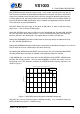
8.3 Data Flow of VS1003
Volume
control
Audio
FIFO
S.rate.conv.
and DAC
R
Bitstream
FIFO
SDI
L
SCI_VOL
SM_ADPCM=0
2048 stereo
samples
MP3/PlusV/
WAV/ADPCM/
WMA decode/
MIDI decode
Bass
enhancer
SB_AMPLITUDE=0
SB_AMPLITUDE!=0
AIADDR = 0
AIADDR != 0
User
Application
ST_AMPLITUDE=0
ST_AMPLITUDE!=0
Treble
enhancer
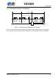
Figure 16: Data Flow of VS1003.
First, depending on the audio data, and provided ADPCM encoding mode is not set, MP3,
WMA, PCM WAV, IMA ADPCM WAV, or MIDI data is received and decoded from the SDI bus.
After decoding, if SCI_AIADDR is non-zero, application code is executed from the address
pointed to by that register. For more details, see Application Notes for VS10XX.
Then data may be sent to the Bass and Treble Enhancer depending on the SCI_BASS register.
After that the signal is fed to the volume control unit, which also copies the data to the Audio
FIFO.
The Audio FIFO holds the data, which is read by the Audio interrupt (Chapter 10.13.1) and fed
to the sample rate converter and DACs. The size of the audio FIFO is 2048 stereo (2×16-bit)
samples, or 8 KiB.
The sample rate converter converts all different sample rates to XTALI/2, or 128 times the
highest usable sample rate. This removes the need for complex PLL-based clocking schemes
and allows almost unlimited sample rate accuracy with one fixed input clock frequency. With
a 12.288 MHz clock, the DA converter operates at 128 × 48 kHz, i.e. 6.144 MHz, and creates
a stereo in-phase analog signal. The oversampled output is low-pass filtered by an on-chip
analog filter. This signal is then forwarded to the earphone amplifier.
8.4 Serial Data Interface (SDI)
The serial data interface is meant for transferring compressed MP3 or WMA data, WAV PCM
and ADPCM data as well as MIDI data.
If the input of the decoder is invalid or it is not received fast enough, analog outputs are auto-
matically muted.
Also several different tests may be activated through SDI as described in Chapter 9.
Version: 1.08, 2014-12-19 27