
User Manual


The ULN2001A is obsolete
a
nd is no longer supplied.
SLRS027G − DECEMBER 1976 − REVISED JUNE 2004
8
POST OFFICE BOX 655303 • DALLAS, TEXAS 75265
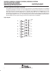
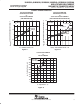
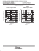
PARAMETER MEASUREMENT INFORMATION
50% 50%
50% 50%
t
PHL
VOLTAGE WAVEFORMS
Input
Output
t
PLH
Figure 9. Propagation Delay-Time Waveforms
Input
Open
V
S
200 Ω
Output
C
L
= 15 pF
(see Note B)
ULN2001A Only
2.7 kΩ
90% 90%
1.5 V 1.5 V
10% 10%
40 µs
≤10 ns≤5 ns
V
IH
(see Note C)
0 V
V
OH
V
OL
Input
Output
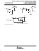
TEST CIRCUIT
VOLTAGE WAVEFORMS
1N3064
2 mH
Pulse
Generator
(see Note A)
ULN2002A
ULN/ULQ2003A
ULN/ULQ2004A
NOTES: A. The pulse generator has the following characteristics: PRR = 12.5 kHz, Z
O
= 50 Ω.
B. C
L
includes probe and jig capacitance.
C. For testing the ULN2001A, the ULN2003A, and the ULQ2003A, V
IH
= 3 V; for the ULN2002A, V
IH
= 13 V;
for the ULN2004A and the ULQ2004A, V
IH
= 8 V.
Figure 10. Latch-Up Test Circuit and Voltage Waveforms