
User Manual

BH1750FVI
Technical Note
9/17
www.rohm.com
2009.04- Rev.B
© 2009 ROHM Co., Ltd. All rights reserved.
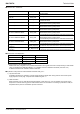
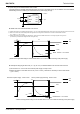
ex 4) LPF using CR is inserted between VCC and DVI.
This method has the possibility that the Reset section of turning on the power supply can not satisfied. cannot be satisfied.
Please design the set considering the characteristic of the power supply enough.
◆ Notes when CR is inserted between VCC and DVI
※ Please note that there is a possibility that reset section ( 1µs ) can not be satisfied because the power supply is turned on when the rise time of VCC is slow
※ When VCC is turned off, the DVI voltage becomes higher than VCC voltage but IC destruction is not occred if recommended constant
( R1 = 1kOhm, C1 = 1µF ) is used.
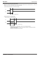
※ Please note that there is a possibility that Reset section (1µsec) cannot be satisfied if wait time is not enough long after turning off VCC.
(It is necessary to consider DVI voltage level after turning off VCC.)
*
Please do the application design to secure Reset section 1us or more after the reclosing of the power supply.
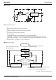
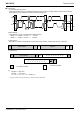
◆
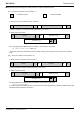
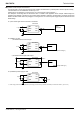
Example of designing set when CR ( C = 1µF, R = 1kΩ ) is inserted between VCC and DVI with VCC=2.8V
①The rise time to 0→2.4V of VCC must use the power supply of 100µs or less.
②Please wait 25ms or more after VCC turn off ( VCC <= 0.05V ), because it is necessary to secure reset section
( 1µs or more ).
R1 : 1kOhm
0.1µF
C1 : 1µF
VCC
ADDR
GND
SCL
DVI
SDA
BH1750FVI
Reset Section : 1us or more
t1
VCC
DVI
2.4V
0.4V
0V
*
Please do the application design to secure Reset section 1us or more after the reclosing of the power supply.
Reset Section : 1us or more
Rise time of power supply : 100us or less
0.05V
Time to power supply reclosing : 25ms or more
れ
VCC
DVI
2.4V
0.4V
2.8V
0V
t2