
User Manual

BH1750FVI
Technical Note
8/17
www.rohm.com
2009.04- Rev.B
© 2009 ROHM Co., Ltd. All rights reserved.
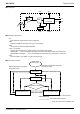
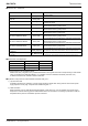
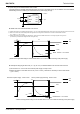
●Application circuit example of DVI terminal
The DVI terminal is an asynchronous reset terminal. Please note that there is a possibility that IC doesn't operate normally
if the reset section is not installed after the start-up of V
CC.
(Please refer to the paragraph of "Timing chart for VCC and DVI power supply sequence" )
The description concerning SDA and the terminal SCL is omitted in this application circuit example. Please design the
application the standard of the I2C bus as it finishes being satisfactory. Moreover, the description concerning the terminal
ADDR is omitted. Please refer to the paragraph of "Timing chart for V
CC and DVI power supply sequence" about the terminal
ADDR design.
ex 1) The control signal line such as CPU is connected.
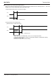
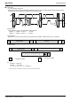
ex 2) Reset IC is used.
1, For Reset IC of the Push-Pull type
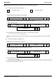
2, For Reset IC of the Open drain output
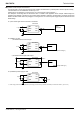
ex 3) A different power supply is used.
※ Power supply of DVI must stand up later than power supply of VCC stand up, because it is necessary to secure reset section ( 1µs or more ).
Micro
Controller
VCC
ADDR
SCL
SDA
0.1µF
0.1µF
DVI
GND
BH1750FVI
BH1750FVI
VCC
ADDR
SCL
SDA
0.1µF
DVI
GND
0.1
µ
F
V2
V1
VCC
ADDR
SCL
SDA
0.1µF
DVI
GND
RESET
Reset IC( Push-Pull type )
BH1750FVI
0.1µF
VCC
ADDR
SCL
SDA
0.1µF
DVI
GND
Reset IC( Open drain type )
RESET
1kOhm
BH1750FVI
0.1
µ
F