
User Manual

BH1750FVI
Technical Note
4/17
www.rohm.com
2009.04- Rev.B
© 2009 ROHM Co., Ltd. All rights reserved.
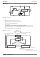
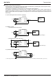
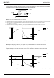
●Block Diagram
●Block Diagram Descriptions
・PD
Photo diode with approximately human eye response.
・AMP
Integration-OPAMP for converting from PD current to Voltage.
・ADC
AD converter for obtainment Digital 16bit data.
・Logic + I
2
C Interface
Ambient Light Calculation and I
2
C BUS Interface. It is including below register.
Data Register → This is for registration of Ambient Light Data. Initial Value is "0000_0000_0000_0000".
Measurement Time Register → This is for registration of measurement time. Initial Value is "0100_0101".
・OSC
Internal Oscillator ( typ. 320kHz ). It is CLK for internal logic.
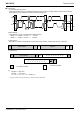
●Measurement Procedure
* "Power On" Command is possible to omit.
SCL
SDA
GND
ADDR
PD
VCC
DVI
Logic
+
I
2
C Interface
ADC
AMP
OSC
State Transition by I
2
C write-command.
Automatically State Transition
State is automatically changed to
Power Down mode.
Power supply
Power Down
Power On
Measurement Command
Initial state is Power Down mode after
VCC and DVI supply.
One Time Measurement
Continuous Measurement