
User Manual

BH1750FVI
Technical Note
2/17
www.rohm.com
2009.04- Rev.B
© 2009 ROHM Co., Ltd. All rights reserved.
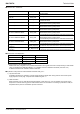
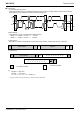
●Electrical Characteristics ( VCC = 3.0V, DVI = 3.0V, Ta = 25℃, unless otherwise noted )
Parameter Symbol Min. Typ. Max. Units Conditions
Supply Current Icc1 - 120 190 µA Ev = 100 lx
※
1
Powerdown Current Icc2 - 0.01 1.0 µA No input Light
Peak Wave Length λp - 560 - nm
Measurement Accuracy S/A 0.96 1.2 1.44 times
Sensor out / Actual lx
EV = 1000 lx
※
1,
※
2
Dark ( 0 lx ) Sensor out S0 0 0 3 count H-Resolution Mode
※
3
H-Resolution Mode Resolution rHR - 1 - lx
L-Resolution Mode Resolution rLR - 4 - lx
H-Resolution Mode Measurement
Time
t
HR - 120 180 ms
L-Resolution Mode Measurement
Time
tLR - 16 24 ms
Incandescent / Fluorescent Sensor
out ratio
rI
F - 1 - times
EV = 1000 lx
ADDR Input ‘H’ Voltage VAH 0.7 * VCC - - V
ADDR Input ‘L’ Voltage VAL - - 0.3 * VCC V
DVI Input ‘L’ Voltage VDVL - - 0.4 V
SCL, SDA Input ‘H’ Voltage 1 VIH1 0.7 * DVI - - V DVI ≧ 1.8V
SCL, SDA Input ‘H’ Voltage 2 VIH2 1.26 - - V 1.65V ≦ DVI <1.8V
SCL, SDA Input ‘L’ Voltage 1 VIL1 - - 0.3 * DVI V DVI ≧ 1.8V
SCL, SDA Input ‘L’ Voltage 2 VIL2 - - DVI – 1.26 V 1.65V ≦ DVI < 1.8V
SCL, SDA, ADDR Input ‘H’ Current IIH
- -
10 µA
SCL, SDA, ADDR Input ‘L’ Current IIL
- -
10 µA
I
2
C SCL Clock Frequency fSCL
- -
400 kHz
I
2
C Bus Free Time tBUF 1.3
-
- µs
I
2
C Hold Time ( repeated ) START
Condition
t
HDSTA 0.6
-
- µs
I
2
C Set up time for a Repeated
START Condition
t
SUSTA 0.6
-
- µs
I
2
C Set up time for a Repeated STOP
Condition
t
SUSTD 0.6
-
- µs
I
2
C Data Hold Time tHDDAT 0
-
0.9 µs
I
2
C Data Setup Time tSUDAT 100
-
- ns
I
2
C ‘L’ Period of the SCL Clock tLOW 1.3
-
- µs
I
2
C ‘H’ Period of the SCL Clock tHIGH 0.6
-
- µs
I
2
C SDA Output ‘L’ Voltage VOL 0
-
0.4 V IOL = 3 mA
※1 White LED is used as optical source.
※2 Measurement Accuracy typical value is possible to change '1' by "Measurement result adjustment function".
※3 Use H-resolution mode or H-resolution mode2 if dark data ( less than 10 lx ) is need.