
User Manual

Revision 1.0 Page 76 of 78
nRF24L01+ Product Specification
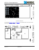
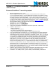
Enhanced ShockBurst™ receive payload
1. Select RX by setting the PRIM_RX bit in the CONFIG register to high. All data pipes that receive
data must be enabled (
EN_RXADDR register), enable auto acknowledgement for all pipes running
Enhanced ShockBurst™ (
EN_AA register), and set the correct payload widths (RX_PW_Px regis-
ters). Set up addresses as described in item 2 in the Enhanced ShockBurst™ transmitting pay-
load example above.
2. Start Active RX mode by setting
CE high.
3. After 130µs nRF24L01+ monitors the air for incoming communication.
4. When a valid packet is received (matching address and correct CRC), the payload is stored in the
RX-FIFO, and the
RX_DR bit in STATUS register is set high. The IRQ pin is active when RX_DR is
high.
RX_P_NO in STATUS register indicates what data pipe the payload has been received in.
5. If auto acknowledgement is enabled, an ACK packet is transmitted back, unless the
NO_ACK bit
is set in the received packet. If there is a payload in the
TX_PLD FIFO, this payload is added to
the ACK packet.
6. MCU sets the
CE pin low to enter standby-I mode (low current mode).
7. MCU can clock out the payload data at a suitable rate through the SPI.
8. nRF24L01+ is now ready for entering TX or RX mode or power down mode.