
User Manual

Revision 1.0 Page 69 of 78
nRF24L01+ Product Specification
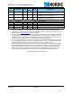
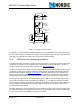
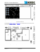
Figure 35. Bottom layer (nRF24L01+ RF layout with single ended connection to PCB antenna and 0402
size passive components
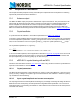
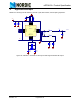
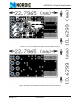
The nest figure (Figure 36., Figure 37. and Figure 38.) is for the SMA output to have a board for direct
measurements at a 50
Ω SMA connector.
Figure 36. Top Overlay (Module with OFM crystal and SMA connector)