
User Manual

Revision 1.0 Page 66 of 78
nRF24L01+ Product Specification
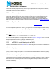
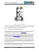
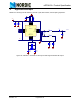
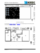
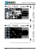
11 Application example
nRF24L01+ with single ended matching network crystal, bias resistor, and decoupling capacitors.
Figure 32. nRF24L01+ schematic for RF layouts with single ended 50
Ω
RF output
C2
22pF
0402
C9
10nF
0402
C8
1nF
0402
R2
22K
0402
VDD
C1
22pF
0402
R1
1M
X1
16 MHz
C7
33nF
0402
L1
8.2nH
0402
C3
2.2nF
0402
C4
4.7pF
0402
L3
3.9nH
0402
L2
2.7nH
0402
C5
1.5pF
0402
C6
1.0pF
0402
CE
1
CSN
2
SCK
3
MOSI
4
MI SO
5
IRQ
6
VDD
7
VSS
8
XC2
9
XC1
10
VDD_PA
11
ANT1
12
ANT2
13
VSS
14
VDD
15
IREF
16
VSS
17
VDD
18
DVDD
19
VSS
20
nRF24L01
U1
NRF24L01
CE
CSN
SCK
MOSI
MI SO
IRQ
50ohm, R
+