
User Manual

Revision 1.0 Page 59 of 78
nRF24L01+ Product Specification
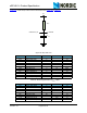
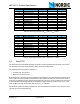
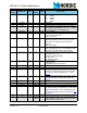
RF_PWR 2:1 11 R/W Set RF output power in TX mode
'00' – -18dBm
'01' – -12dBm
'10' – -6dBm
'11' – 0dBm
Obsolete 0 Don’t care
07 STATUS Status Register (In parallel to the SPI command
word applied on the
MOSI pin, the STATUS register
is shifted serially out on the
MISO pin)
Reserved 7 0 R/W Only '0' allowed
RX_DR 6 0 R/W Data Ready RX FIFO interrupt. Asserted when
new data arrives RX FIFO
c
.
Write 1 to clear bit.
TX_DS 5 0 R/W Data Sent TX FIFO interrupt. Asserted when
packet transmitted on TX. If
AUTO_ACK is acti-
vated, this bit is set high only when ACK is
received.
Write 1 to clear bit.
MAX_RT 4 0 R/W Maximum number of TX retransmits interrupt
Write 1 to clear bit. If
MAX_RT is asserted it must
be cleared to enable further communication.
RX_P_NO 3:1 111 R Data pipe number for the payload available for
reading from
RX_FIFO
000-101: Data Pipe Number
110: Not Used
111: RX FIFO Empty
TX_FULL 0 0 R TX FIFO full flag.
1: TX FIFO full.
0: Available locations in TX FIFO.
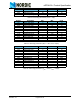
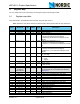
08 OBSERVE_TX Transmit observe register
PLOS_CNT 7:4 0 R Count lost packets. The counter is overflow pro-
tected to 15, and discontinues at max until reset.
The counter is reset by writing to
RF_CH. See
page 75
.
ARC_CNT 3:0 0 R Count retransmitted packets. The counter is reset
when transmission of a new packet starts. See
page 75
.
09 RPD
Reserved 7:1 000000 R
RPD 0 0 R Received Power Detector. This register is called
CD (Carrier Detect) in the nRF24L01. The name is
different in nRF24L01+ due to the different input
power level threshold for this bit. See section 6.4
on page 25.
0A RX_ADDR_P0 39:0 0xE7E7E
7E7E7
R/W Receive address data pipe 0. 5 Bytes maximum
length. (LSByte is written first. Write the number of
bytes defined by SETUP_AW)
Address
(Hex)
Mnemonic Bit
Reset
Value
Type Description