
User Manual

Revision 1.0 Page 56 of 78
nRF24L01+ Product Specification
You can write to the TX FIFO using these three commands; W_TX_PAYLOAD and
W_TX_PAYLOAD_NO_ACK in PTX mode and W_ACK_PAYLOAD in PRX mode. All three commands provide
access to the
TX_PLD register (see Table 28. on page 63. for details of this register).
The RX FIFO can be read by the command
R_RX_PAYLOAD in PTX and PRX mode. This command pro-
vides access to the
RX_PLD register.
The payload in TX FIFO in a PTX is not removed if the
MAX_RT IRQ is asserted.
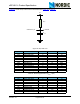
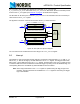
Figure 30. FIFO (RX and TX) block diagram
You can read if the TX and RX FIFO are full or empty in the FIFO_STATUS register.
8.5 Interrupt
The nRF24L01+ has an active low interrupt (IRQ) pin. The IRQ pin is activated when TX_DS IRQ, RX_DR
IRQ or MAX_RT IRQ are set high by the state machine in the STATUS register. The IRQ pin resets when
MCU writes '1' to the IRQ source bit in the
STATUS register. The IRQ mask in the CONFIG register is used
to select the IRQ sources that are allowed to assert the
IRQ pin. By setting one of the MASK bits high, the
corresponding IRQ source is disabled. By default all IRQ sources are enabled.
Note: The 3 bit pipe information in the STATUS register is updated during the IRQ pin high to low
transition. The pipe information is unreliable if the
STATUS register is read during an IRQ pin
high to low transition.
Data
TX FIFO
32 byte
32 byte
32 byte
TX FIFO Controller
Data
Control
SPI
command
decoder
RX FIFO
32 byte
32 byte
32 byte
RX FIFO Controller
Data Data
Control
SPI