
User Manual

Revision 1.0 Page 52 of 78
nRF24L01+ Product Specification
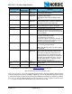
Note: The 3 bit pipe information in the STATUS register is updated during the IRQ pin high to low
transition. The pipe information is unreliable if the
STATUS register is read during an IRQ pin
high to low transition.
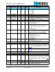
8.3.2 SPI timing
SPI operation and timing is shown in Figure 26. to Figure 28. and in Table 22. to Table 27.. nRF24L01+
must be in a standby or power down mode before writing to the configuration registers.
In Figure 26.
to Figure 28. the following abbreviations are used:
Table 21. Abbreviations used in Figure 26. to Figure 28.
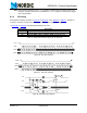
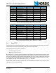
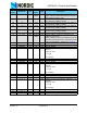
Figure 26. SPI read operation
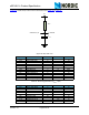
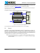
Figure 27. SPI write operation
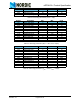
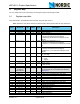
Figure 28. SPI NOP timing diagram
Abbreviation Description
Cn SPI command bit
Sn
STATUS register bit
Dn Data Bit (
Note: LSByte to MSByte, MSBit in each byte first)
C7 C6 C5 C4 C3 C2 C1 C0
S7 S6 S5 S4 S3 S2 S1 S0 D7 D6 D5 D4 D3 D2 D1 D0
D15
D14 D1 3 D1 2
D1 1 D1 0
D9 D8
CSN
SCK
MOSI
MISO
C7 C6 C5 C4 C3 C2 C1 C0 D7 D6 D5 D4 D3 D2 D1 D0 D1 5 D1 4 D13 D12 D11 D1 0 D9 D8
S7 S6 S5 S4 S3 S2 S1 S0
CSN
SCK
MO SI
MISO
C7 C6 C0
S7 S0
TcdzTcdTcsd
Tdh
Tdc
TcchTclTclTchTcc Tch
TcwhTcwh
CSN
SCK
MOSI
MISO