
User Manual

Revision 1.0 Page 35 of 78
nRF24L01+ Product Specification
7.5 Enhanced ShockBurst flowcharts
This section contains flowcharts outlining PTX and PRX operation in Enhanced ShockBurst™.
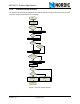
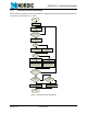
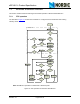
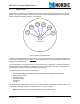
7.5.1 PTX operation
The flowchart in Figure 10. outlines how a nRF24L01+ configured as a PTX behaves after entering
standby-I mode.
Note: ShockBurst™ operation is outlined with a dashed square.
Figure 10. PTX operations in Enhanced ShockBurst™
Start Primary TX
Standby-I mode
Standby-II mode
CE=1
Packet in TX
FIFO?
Transmit Packet
Is Auto Re-
Transmit
enabled?
RX mode and
packet
disassembly
Yes
Yes
Yes
No
Packet in TX
FIFO?
No
Is an ACK
received?
Timeout?
Has ARD
elapsed?
Yes
Standby-II mode
TX mode
Retransmit last
packet
TX Settling and
packet assembly
Packet in TX
FIFO?
Yes
Is CE =1?
No
Is CE =1?
No
Yes
No
YesNo
Yes
TX Settling
Number of
retries = ARC?
No
RX Settling
Set MAX_RT IRQ
No
No
Yes
Set TX_DS IRQ
Yes
Has the ACK
payload?
Put payload in RX
FIFO.
Set TX_DS IRQ
and RX_DR IRQ
Set TX_DS IRQ
Yes
No
No_ACK?
No
Yes
NoYes
ShockBurst operation