
User Manual

Revision 1.0 Page 28 of 78
nRF24L01+ Product Specification
7.3 Enhanced Shockburst™ packet format
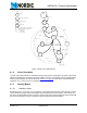
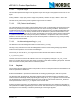
The format of the Enhanced ShockBurst™ packet is described in this section. The Enhanced Shock-
Burst™ packet contains a preamble, address, packet control, payload and CRC field. Figure 5.
shows the
packet format with MSB to the left.
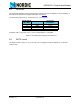
Figure 5. An Enhanced ShockBurst™ packet with payload (0-32 bytes)
7.3.1 Preamble
The preamble is a bit sequence used to synchronize the receivers demodulator to the incoming bit stream.
The preamble is one byte long and is either 01010101 or 10101010. If the first bit in the address is 1 the
preamble is automatically set to 10101010 and if the first bit is 0 the preamble is automatically set to
01010101. This is done to ensure there are enough transitions in the preamble to stabilize the receiver.
7.3.2 Address
This is the address for the receiver. An address ensures that the packet is detected and received by the
correct receiver, preventing accidental cross talk between multiple nRF24L01+ systems. You can configure
the address field width in the AW register to be 3, 4 or 5 bytes, see Table 28. on page 63
.
Note: Addresses where the level shifts only one time (that is, 000FFFFFFF) can often be detected in
noise and can give a false detection, which may give a raised Packet Error Rate. Addresses
as a continuation of the preamble (hi-low toggling) also raises the Packet Error Rate.
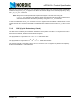
7.3.3 Packet control field
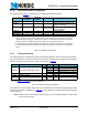
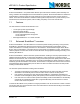
Figure 6. shows the format of the 9 bit packet control field, MSB to the left.
Figure 6. Packet control field
The packet control field contains a 6 bit payload length field, a 2 bit PID (Packet Identity) field and a 1 bit
NO_ACK flag.
Preamble 1 byte Address 3-5 byte
9 bit
Payload 0 - 32 byte
CRC 1-2
byte
Packet Control Field
NO_ACK 1bitPID 2bitPayload length 6bit