
User Manual

Revision 1.0 Page 25 of 78
nRF24L01+ Product Specification
6.2 Air data rate
The air data rate is the modulated signaling rate the nRF24L01+ uses when transmitting and receiving
data. It can be 250kbps, 1Mbps or 2Mbps. Using lower air data rate gives better receiver sensitivity than
higher air data rate. But, high air data rate gives lower average current consumption and reduced probabil-
ity of on-air collisions.
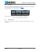
The air data rate is set by the RF_DR bit in the RF_SETUP register. A transmitter and a receiver must be
programmed with the same air data rate to communicate with each other.
nRF24L01+ is fully compatible with nRF24L01. For compatibility with nRF2401A, nRF2402, nRF24E1, and
nRF24E2 the air data rate must be set to 250kbps or 1Mbps.
6.3 RF channel frequency
The RF channel frequency determines the center of the channel used by the nRF24L01+. The channel
occupies a bandwidth of less than 1MHz at 250kbps and 1Mbps and a bandwidth of less than 2MHz at
2Mbps. nRF24L01+ can operate on frequencies from 2.400GHz to 2.525GHz. The programming resolu-
tion of the RF channel frequency setting is 1MHz.
At 2Mbps the channel occupies a bandwidth wider than the resolution of the RF channel frequency setting.
To ensure non-overlapping channels in 2Mbps mode, the channel spacing must be 2MHz or more. At
1Mbps and 250kbps the channel bandwidth is the same or lower than the resolution of the RF frequency.
The RF channel frequency is set by the RF_CH register according to the following formula:
F
0
= 2400 + RF_CH [MHz]
You must program a transmitter and a receiver with the same RF channel frequency to communicate with
each other.
6.4 Received Power Detector measurements
Received Power Detector (RPD), located in register 09, bit 0, triggers at received power levels above -64
dBm that are present in the RF channel you receive on. If the received power is less than -64 dBm,
RDP = 0.
The RPD can be read out at any time while nRF24L01+ is in receive mode. This offers a snapshot of the
current received power level in the channel. The RPD status is latched when a valid packet is received
which then indicates signal strength from your own transmitter. If no packets are received the RPD is
latched at the end of a receive period as a result of host MCU setting CE low or RX time out controlled by
Enhanced ShockBurst™.
The status of RPD is correct when RX mode is enabled and after a wait time of Tstby2a +Tdelay_AGC=
130us + 40us. The RX gain varies over temperature which means that the RPD threshold also varies over
temperature. The RPD threshold value is reduced by - 5dB at T = -40°C and increased by + 5dB at 85°C.