
User Manual

Revision 1.0 Page 24 of 78
nRF24L01+ Product Specification
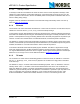
6.1.6 Operational modes configuration
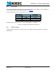
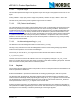
The following table (Table 15.) describes how to configure the operational modes.
Table 15. nRF24L01+ main modes
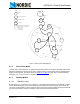
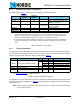
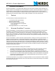
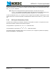
6.1.7 Timing Information
The timing information in this section relates to the transitions between modes and the timing for the CE
pin. The transition from TX mode to RX mode or vice versa is the same as the transition from the standby
modes to TX mode or RX mode (max. 130µs), as described in Table 16.
Table 16. Operational timing of nRF24L01+
For nRF24L01+ to go from power down mode to TX or RX mode it must first pass through stand-by mode.
There must be a delay of Tpd2stby (see Table 16.
) after the nRF24L01+ leaves power down mode before
the CE is set high.
Note: If VDD is turned off the register value is lost and you must configure nRF24L01+ before enter-
ing the TX or RX modes.
Mode
PWR_UP
register
PRIM_RX
register
CE input pin FIFO state
RX mode111-
TX mode 1 0 1 Data in TX FIFOs. Will empty all
levels in TX FIFOs
a
.
a. If CE is held high all TX FIFOs are emptied and all necessary ACK and possible retransmits are car-
ried out. The transmission continues as long as the TX FIFO is refilled. If the TX FIFO is empty when
the CE is still high, nRF24L01+ enters standby-II mode. In this mode the transmission of a packet is
started as soon as the
CSN is set high after an upload (UL) of a packet to TX FIFO.
TX mode 1 0 Minimum 10µs
high pulse
Data in TX FIFOs.Will empty one
level in TX FIFOs
b
.
b. This operating mode pulses the CE high for at least 10µs. This allows one packet to be transmitted.
This is the normal operating mode. After the packet is transmitted, the nRF24L01+ enters standby-I
mode.
Standby-II 1 0 1 TX FIFO empty.
Standby-I 1 - 0 No ongoing packet transmission.
Power Down 0 - - -
Name nRF24L01+ Notes Max. Min. Comments
Tpd2stby Power Down Î Standby mode
150µs With external clock
a
a. See Table 11. on page 19 for crystal specifications.
1.5ms External crystal, Ls < 30mH
3ms External crystal, Ls = 60mH
4.5ms External crystal, Ls = 90mH
Tstby2a Standby modes Î TX/RX mode 130µs
Thce Minimum CE high 10µs
Tpece2csn Delay from CE positive edge to CSN
low
4µs