
User Manual

Revision 1.0 Page 21 of 78
nRF24L01+ Product Specification
6 Radio Control
This chapter describes the nRF24L01+ radio transceiver’s operating modes and the parameters used to
control the radio.
The nRF24L01+ has a built-in state machine that controls the transitions between the chip’s operating
modes. The state machine takes input from user defined register values and internal signals.
6.1 Operational Modes
You can configure the nRF24L01+ in power down, standby, RX or TX mode. This section describes these
modes in detail.
6.1.1 State diagram
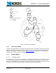
The state diagram in Figure 4. shows the operating modes and how they function. There are three types of
distinct states highlighted in the state diagram:
• Recommended operating mode: is a recommended state used during normal operation.
• Possible operating mode: is a possible operating state, but is not used during normal operation.
• Transition state: is a time limited state used during start up of the oscillator and settling of the PLL.
When the VDD reaches 1.9V or higher nRF24L01+ enters the Power on reset state where it remains in
reset until entering the Power Down mode.