
User Manual

Revision 1.0 Page 15 of 78
nRF24L01+ Product Specification
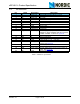
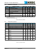
5.2 General RF conditions
Table 5. General RF conditions
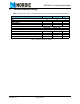
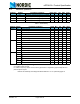
5.3 Transmitter operation
Table 6. Transmitter operation
Symbol Parameter (condition) Notes Min. Typ. Max. Units
f
OP
Operating frequency
a
a. Regulatory standards determine the band range you can use.
2400 2525 MHz
PLL
res
PLL Programming resolution 1 MHz
f
XTAL
Crystal frequency 16 MHz
Δf
250
Frequency deviation @ 250kbps ±160 kHz
Δf
1M
Frequency deviation @ 1Mbps ±160 kHz
Δf
2M
Frequency deviation @ 2Mbps ±320 kHz
R
GFSK
Air Data rate
b
b. Data rate in each burst on-air
250 2000 kbps
F
CHANNEL 1M
Non-overlapping channel spacing @ 250kbps/
1Mbps
c
c. The minimum channel spacing is 1MHz
1MHz
F
CHANNEL 2M
Non-overlapping channel spacing @ 2Mbps
c
2MHz
Symbol Parameter (condition) Notes Min. Typ. Max. Units
P
RF
Maximum Output Power
a
a. Antenna load impedance = 15Ω+j88Ω
0+4dBm
P
RFC
RF Power Control Range 16 18 20 dB
P
RFCR
RF Power Accuracy ±4 dB
P
BW2
20dB Bandwidth for Modulated Carrier (2Mbps) 1800 2000 kHz
P
BW1
20dB Bandwidth for Modulated Carrier (1Mbps) 900 1000 kHz
P
BW250
20dB Bandwidth for Modulated Carrier (250kbps) 700 800 kHz
P
RF1.2
1
st
Adjacent Channel Transmit Power 2MHz
(2Mbps)
-20 dBc
P
RF2.2
2
nd
Adjacent Channel Transmit Power 4MHz
(2Mbps)
-50 dBc
P
RF1.1
1
st
Adjacent Channel Transmit Power 1MHz
(1Mbps)
-20 dBc
P
RF2.1
2
nd
Adjacent Channel Transmit Power 2MHz
(1Mbps)
-45 dBc
P
RF1.250
1
st
Adjacent Channel Transmit Power 1MHz
(250kbps)
-30 dBc
P
RF2.250
2
nd
Adjacent Channel Transmit Power 2MHz
(250kbps)
-45 dBc