
User Manual

Revision 1.0 Page 14 of 78
nRF24L01+ Product Specification
5 Electrical specifications
Conditions: VDD = +3V, VSS = 0V, T
A
= - 40ºC to + 85ºC
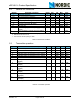
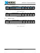
5.1 Power consumption
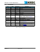
Table 4. Power consumption
Symbol Parameter (condition) Notes Min. Typ. Max. Units
Idle modes
I
VDD_PD
Supply current in power down 900 nA
I
VDD_ST1
Supply current in standby-I mode
a
a. This current is for a 12pF crystal. Current when using external clock is dependent on signal swing.
26 µA
I
VDD_ST2
Supply current in standby-II mode 320 µA
I
VDD_SU
Average current during 1.5ms crystal
oscillator startup
400 µA
Transmit
I
VDD_TX0
Supply current @ 0dBm output power
b
b. Antenna load impedance = 15Ω+j88Ω..
11.3 mA
I
VDD_TX6
Supply current @ -6dBm output
power
b
9.0 mA
I
VDD_TX12
Supply current @ -12dBm output
power
b
7.5 mA
I
VDD_TX18
Supply current @ -18dBm output
power
b
7.0 mA
I
VDD_AVG
Average Supply current @ -6dBm out-
put power, ShockBurst™
c
c. Antenna load impedance = 15Ω+j88Ω. Average data rate 10kbps and max. payload length packets.
0.12 mA
I
VDD_TXS
Average current during TX settling
d
d. Average current consumption during TX startup (130µs) and when changing mode from RX to TX
(130µs).
8.0 mA
Receive
I
VDD_2M
Supply current 2Mbps 13.5 mA
I
VDD_1M
Supply current 1Mbps 13.1 mA
I
VDD_250
Supply current 250kbps 12.6 mA
I
VDD_RXS
Average current during RX settling
e
e. Average current consumption during RX startup (130µs) and when changing mode from TX to RX
(130µs).
8.9 mA