
User Manual
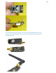

BOTTOM VIEW
Above is the version with Transmit Power amplifier and Receive Preamplifier. Our low-
cost antenna is on the unit shown on the right. The same 8 pins connect to Arduino and
the same software is used.
Here's a link to a Home-Brew antenna design:
These transcevers use the 2.4 GHz unlicensed band like many WiFi routers, some
cordless phones etc.
Transceivers like these both send and receive data in 'packets' of several bytes at a
time. There is built-in error correction and resending, and it is possible to have one
unit communicate with up to 6 other similar units at the same time.
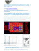
These amazing low-cost units have a lot of internal complexity but some talented
people have written Arduino libraries that make them easy to us. We have other pages
that show examples and point to the free software libraries you may need. They all use
the same pinout as shown in the following diagram, which is a TOP VIEW
(Correction!):
Here's details of the Pinout and connections to Arduino
(updated):
Signal RF Module COLOR Arduino pin for
RF24 Library
Arduino pin for
Mirf Library
GND 1 Brown GND GND
VCC 2 Red 3.3V 3.3V
CE 3 Orange 9 8
CSN 4 Yellow 10 7
SCK 5 Green 13 13
MOSI 6 Blue 11 11
MISO 7 Violet 12 12
IRQ 8 Gray 2 *
NOTE: Pin 8 IRQ is Unused by most software, but the
RF24 library has an example that utilizes it.
The COLOR is for optional color-coded flat cable such as THIS. We'll add some
You are not a member of this wiki. Join now Dism iss
Sign In (http://www.wikispaces.com/site/signin?goto=http%3A%2F%2Farduino-info.wikispaces .com%2FNrf24L01-2.4GHz-HowTo)