
Instructions / Assembly


ASSEMBLY INSTRUCTIONS
1. Locate the three separate heat plate pieces. Lay the plates on a flat surface as shown in Figure 1. Place the rounded
inner edge of one plate against the vertical jet pipe. The bottom of the plate should be located above the the prongs
when installed (3 prongs welded to side of jet pipe.) The plate will fit around the appliance leg using the cutouts
provided on the plate. Repeat procedure with the second plate. Align the bolt holes of the first and second plates
and attach with bolt, lock washer and nut. Repeat procedure with the third plate. Tighten all bolts/nuts. Reference
Figure 2 and Figure 3 for picture of heat plate assembly.
10
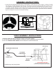
HOSE ASSEMBLY INSTRUCTIONS
1. Wrench tighten the 3/8” female flare swivel to the brass adapter.
2. The hose to burner (brass adapter) connection must be tightened and leak tested.
3. Go to the Use and Care Section of this manual for further instructions.
Leg
Cutouts
Bolt
Holes
Vertical Heat Plate
Cutout
Vertical Heat Plate
Figure 1
Figure 2
* Models may vary from picture.
JET PIPE (2)
3/8 FEMALE
FLARE SWIVEL
ORIFICE CAP (2)
(DO NOT REMOVE THIS FITTING)
The orifice is the drilled hole in the brass cap
which should be pointing up directly into the jet pipe.
BRASS
ADAPTER
ADJUSTABLE REGULATOR
TYPE 1
CONNECTION
Figure 3