
User Manual

USB Battery Charger
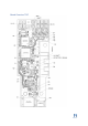
To test if the battery charger is working 5V is applied over TP3(5V) and TP2(GND). If pads
5
+(VBATT) and –(GND) will have approx. 4.2V across the battery charger is functioning
properly.
LDO Power
To test if the battery charger is working 5V is applied over with POGO pins connected to
6
TP3(5V) and TP2(GND). If POGO pins connected to TP(1) or TP9(2V8) will have 2.8V
across it to TP2(GND) the LDO is functioning properly.
Battery power
To test if the battery power is functioning 4,2V is applied over pads +(VBATT) and –(GND). If
TP(1) or TP9(2V8) will have 2.8V across it to TP2(GND) battery power is functioning
properly.
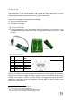
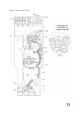
DC motor
Up to three small brushed DC motors can be controlled by the FeelChip D board. The motors
are driven by three N-channel MOSFETs with designators Q1, Q2, Q3 (MPN: BSS806N) with
a maximum voltage of 3.3V and a maximum current of 3A. PWM can be applied to each of
these channels.
5
Designator in schematic = U5 and part number is MPC7382
6
Designator in schematic = U5 and part number is MPC7382