FeelChip-D Manual Maurice Op de Beek version 1 , 20190607
Table of Contents Introduction 3 Programming 4 Tag-Connect PCB Pads Board Overview TOP 4 5 TOP Parts 6 TOP Pads 7 Board overview BOTTOM 8 BOTTOM Parts 9 BOTTOM Pads 9 USB Battery Charger 10 LDO Power 10 Battery power 10 DC motor 10 FCC information 11
Introduction The FeelChip D is PCBA board designed for the haptic industry. It has 3 motor channels and 5 touch channels. The FeelChip D is equipped with: 1. 2. 3. 4. 5. 6. a LIPO charging unit a. 5 volt RGB LED light a. Charging (red) b. Almost empty (blinking red) c. Bluetooth (blue) d. Charged (green) Press Button a. Turn the device on/off b. Switch through patterns Programmer a. Pin to program the ESP32 MPR121 a.
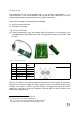
Programming 1 The FeelChip-D-2p can be programmed with a Tag connect TC2030-IDC-NL or a 2 TC2030-MCP-NL on the small footprint PCB Tag-Connect PAD. Alternatively it can be programmed using the test pads with the aid of a Pogo Pin test setup. There are two methods to programming the FeelChipD: , 1) Via Tag-Connect PCB pads 2) Via Pogo-Pin Test pads Tag-Connect PCB Pads For manual programming, the Feel Robotics ESP32 programmer is used which is only 3 compatible with the TC2030-MCP-NL cable.
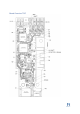
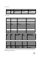
Board Overview TOP
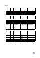
TOP Parts PART PART PART PART PART PART PART UNIT U1 U2 U3 U4 U5 U6 PART NUMBER ESP32-D0WDQ6 WS25Q32JVSSIQ AP7361 Removed MPC7382 MPR121QR2 FUNCTION MCU FLASH LDO Removed Lipo Charger TOUCH DESCRIPTION Main processor Flash memory Voltage regulator UNIT RT1 Y1 PART NUMBER MSMF050 CLOCK FUNCTION PTC Reset Fuse CLOCK DESCRIPTION FUNCTION N-Channel Mosfet N-Channel Mosfet N-Channel Mosfet N-Channel Mosfet DESCRIPTION Drives Motor 1 Drives Motor 2 Drives Motor 3 On/Off Control P-Channel Mosfet P-Chann
TOP Pads PAD PAD PAD PAD PAD PAD PAD J1(1) J1(2) J1(3) J1(4) J1(5) PART NUMBER Touch PAD 1 Touch PAD 2 Touch PAD 3 Touch PAD 4 Touch PAD 5 NET Touch 4 Touch 5 Touch 2 Touch 3 Touch 1 DESCRIPTION MPR121 Electrode 6 MPR121 Electrode 7 MPR121 Electrode 4 MPR121 Electrode 5 MPR121 Electrode 3 PAD J2(1) J2(2) J2(3) J2(4) J2(5) J2(6) PART NUMBER Motor PAD 1 Motor PAD 2 Motor PAD 3 Motor PAD 4 Motor PAD 5 Motor PAD 6 NET VBATT MTR 1 VBATT MTR 2 VBATT MTR 3 DESCRIPTION PAD W1 W2 PART NUMBER Button PAD 1 B
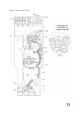
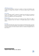
Board overview BOTTOM
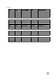
BOTTOM Parts PART PART PART UNIT S1 DS1 PART J4 PART NUMBER B3FS-1010 AAA3528LSEEZGK QBKS SM02B-SRSS-TB FUNCTION Tactile Switch RGB LED DESCRIPTION Tactile Switch RGB LED Shrouded Header USB 5V Table 10 - Switches BOTTOM Pads Testpoint TP1 Net Name 2V8 TP2 TP3 GND 5Vin TP4 TP5 TP6 TP7 TP8 TP9 RED 2 BLUE 2 GREEN 2 EN IO0/PwrOn 2V8 TP10 TP11 ESP_RX ESP_TX Function LDO Voltage source 2.8V Ground USB Voltage source 5.
USB Battery Charger To test if the battery charger5 is working 5V is applied over TP3(5V) and TP2(GND). If pads +(VBATT) and –(GND) will have approx. 4.2V across the battery charger is functioning properly. LDO Power To test if the battery charger6 is working 5V is applied over with POGO pins connected to TP3(5V) and TP2(GND). If POGO pins connected to TP(1) or TP9(2V8) will have 2.8V across it to TP2(GND) the LDO is functioning properly.
FCC information The OEM integrator is still responsible for testing their end-product for any additional compliance requirements required with this module installed. Host manufacturer (OEM) is responsible for ensuring that the host continues to be compliant with the Part 15 subpart B unintentional radiator requirements after the module is installed and operational. The grantee's FCC ID can be used only when all FCC compliance requirements are met.