
Instructions / Assembly
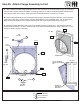
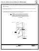

Step 26: Attach Flange Assembly to Fort
Hardware
14 x #12 x 1” Pan Screw
4 x #12 x 2” Pan Screw
8 x #12 Screw Bezel
S7
(hidden)
S6
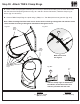
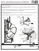
A: With a helper place the Flange Assembly ush to the Crowsnest on the fort as shown in g. 26.1 and 26.5,
then pre-drill 1/8” pilot holes in the bottom 4 mounting locations on (230) Crowsnest Gap Board (approximate
spots where circles are on gure), making sure the pre-drilled holes are a minimum of 1” deep.
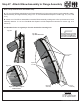
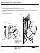
B: Attach Flange Assembly to the Crowsnest through (230) Crowsnest Gap Board and into (210) Crowsnest
Front using 4 (S7) #12 x 2” Pan Screws (with #12 Screw Bezel) in the pre-drilled holes. (g. 26.1 and 26.2)
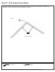
Make sure the at surfaces of the Flange Assembly are ush to the Crowsnest as shown in g. 26.5.
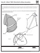
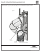
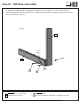
C: Attach the Flange Assembly ush to (212) Crowsnest Top using 4 (S6) #12 x 1” Pan Screws (with #12
Screw Bezel) as shown in g. 25.1 and 25.3 and to both (240) Crowsnest Spacers using 5 (S6) #12 x 1” Pan
Screw per board. (g. 26.1 and 26.4)
Flange
Assembly
S7
FW6
FW6
FW6
Bottom
Sides
Top
212
240
210
212
Bottom of
slideush
with deck
Topofslideush
to(212)Crowsnest
Top
Fig. 26.1
Fig. 26.6
Fig. 26.4
Fig. 26.3
Fig. 26.2
Fig. 26.5
(hidden)
Outside View
Inside View
S6
S6
(hidden)
240
240
240
230
71 europecustomerservice@kidkraft.com