
User's Manual

Component Descriptions
September 2013 2-66 P/N 81-CO2MAN-001
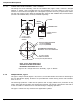
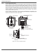
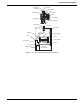
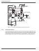
2-8.3 Pneumatic Discharge Delay
This pneumatic discharge delay (Figure 2-71 through Figure 2-73) uses CO
2
system pressure
or N
2
actuation pressure to provide a pneumatic (automatic mechanical) means to delay the
CO
2
discharge for a pre-determined period. The pneumatic discharge delay consists of a
metering tube, a cylinder, and a differential pressure operated valve with a control port for
attaching a compatible control head. This assembly is installed downstream of pressure
operated equipment, but upstream of the nozzle, to allow alarms to sound, and equipment and
ventilation to shut down prior to the carbon-dioxide discharge.
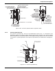
Discharge delay assemblies are available with non-adjustable, factory pre-set delay periods.
Attachment of a compatible control head allows the delay period to be bypassed. Without a
control head the delay period cannot be bypassed.
Consult NFPA 12 (latest edition) for guidance selecting appropriate control heads.
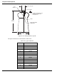
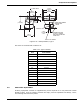
Figure 2-71. Pneumatic Discharge Delay
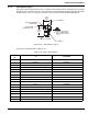
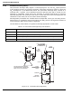
Table 2-32. Pneumatic Discharge Delay Part Numbers
Part Number Description
81-871071-000 CO2 Discharge Delay, 30 Second (Not FM Approved)
81-897636-000 CO2 Discharge Delay, 60 Second (Not FM Approved)
81-871072-001 N2 Discharge Delay, 30 Second (For Use w/108-cuin N2 Cylinder Only)
81-871072-002 N2 Discharge Delay, 60 Second (For Use w/108-cuin N2 Cylinder Only)
OUT
IN
4-7/16 in.
(113 mm)
1-1/4 in. - 18 NF-3 MAKE
FOR ATTACHMENT
OF CONTROL HEAD
TO OVERRIDE DELAY
OUTLET
3/4 in. NPT
FEMALE
INLET
3/4 in. NPT
FEMALE
FILTER
NAMEPLATE
PRESSURE
ACCUMULATOR
TYPICAL
METERING TUBE
(P/N 81-871071-000
SHOWN)
INLET AND OUTLET MAY BE REDUCED
WITH BUSHING OR BELL REDUCER AND
NIPPLE TO 1/2 in. NPT IF NECESSARY
VALVE
17-7/8 IN.
(454 mm)
3-9/16 in.
(90 mm)
DIA.