
User's Manual

Component Descriptions
September 2013 2-48 P/N 81-CO2MAN-001
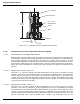
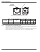
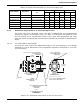
2-5.2.2 4-INCH VALVE
The 4-inch valve, Part No. 81-890208-000 (Figure 2-53), has flanged inlet and outlet ports
that require the flanges, gaskets and fasteners described in Paragraph 2-5.2.3,
Paragraph 2-5.2.4 and Paragraph 2-5.2.5 for connection to the distribution piping.
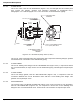
Figure 2-53. Directional (Stop) Valve (4-inch)
The 4-inch valve has flanged inlet and outlet ports that require the following flanges, gaskets
and fasteners for connection to the distribution piping.
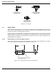
2-5.2.3 4-INCH FLANGE
The 4-inch welding neck flange, Part No. WK-681016-000 (Figure 2-53), is required to attach
the 4-inch directional (or stop) valve to 4-inch distribution piping. Two flanges are required per
valve.
2-5.2.4 4-INCH GASKET
The 4-inch flange gasket, Part No. WK-200150-000 (Figure 2-53), is required to seal the
connection between the 4-inch directional valve and the 4-inch welding neck flange. Two
gaskets are required per valve.
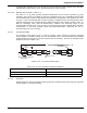
2-5.2.5 NUTS AND BOLTS
7/8-inch hex nuts, Part No WK-152356-000 (Figure 2-53), and 7/8-inch by 5-inch long bolts,
Part No. WK-196656-800 (Figure 2-53), are required to connect the 4-inch welding neck
flanges to the 4-inch directional valve. A total of 16 nuts and bolts are required per valve.
INLET
7/8 in. X 5 in. (127 mm) LG. HEX BOLT
P/N WK-196656-800
16 REQUIRED
12-1/8 in.
(308 mm)
OUTLET
7/8 in. HEX NUT
P/N WK-152356-000
16 REQUIRED
GASKET
P/N WK-200150-000
2 REQUIRED
4 in. WELDING NECK FLANGE
P/N WK-681016-000
2 REQUIRED
SIDE VIEW
WITHOUT
ASSEMBLED FLANGE
10-3/4 in. (273 mm) DIAMETER FLANGE
8-1/2 in. (216 mm) BOLT CIRCLE
11-1/16 in.
(281 mm)
1-1/4 in. - 18 NF-3 MALE
FOR CONTROL HEAD
CONNECTION