
User's Manual

Component Descriptions
P/N 81-CO2MAN-001 2-47 September 2013
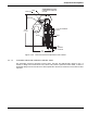
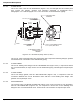
2-5.2 Directional (Stop) Valves (2 1/2-inch through 4-inch)
The 3-inch and 4-inch directional valves, Part Nos. 81-890010-000 and 81-890208-000
respectively (Figure 2-52 and Figure 2-53), are similar in construction and operation as the
1/2-inch through 2-inch size directional valves. These valves have flanged inlet and outlet
ports and require two appropriately-sized flanges and gaskets for connection to the distribution
piping.
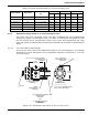
2-5.2.1 2 1/2-INCH AND 3-INCH VALVES
For the 3-inch valve, Part No. 81-890010-000 (Figure 2-52), see Paragraph 2-4.3.1 through
Paragraph 2-4.3.4 for descriptions of the components required for connection to 2 1/2-inch
and 3-inch piping.
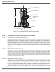
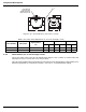
Figure 2-52. Directional (Stop) Valves (2-1/2-inch and 3-inch)
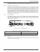
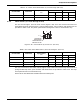
Table 2-20. Check Valve Dimensions (1 1/2-inch through 2-inch)
Part Number Valve Size
Pipe Thread
“D”
“A” “B” “C”
in. mm in. mm in. mm
81-870023-000 1/2 in. 1/2 in. - 14 NPT 3.75 95 2.50 64 4.68 119
81-870022-000 3/4 in. 3/4 in. - 14 NPT 4.25 108 2.81 71 5.68 144
81-870122-000 1 in. 1 in. - 11.5 NPT 5.50 140 3.62 92 6.87 175
81-870032-000 1-1/4 in. 1-1/4 in. - 11.5 NPT 5.50 140 3.62 92 6.87 175
81-800123-000 1-1/2 in. 1-1/2 in. - 11.5 NPT 7.50 191 4.75 121 8.43 214
81-800049-000 2 in. 2 in. - 11.5 NPT 7.50 191 4.75 121 8.43 214
INLET
3/4 in. X 4-1/2 in. (114 mm) LG. HEX BOLT
P/N WK-196648-720
16 REQUIRED
10-1/2 in.
(267 mm)
OUTLET
3/4 in. HEX NUT
P/N WK-152308-000
16 REQUIRED
GASKET
P/N WK-200973-000
2 REQUIRED
2-1/2 in. WELDING NECK FLANGE
P/N WK-263716-000
2 REQUIRED
-OR-
3 in. WELDING NECK FLANGE
P/N WK-681012-000
2 REQUIRED
SIDE VIEW
WITHOUT
ASSEMBLED FLANGE
8-1/4 in. (210 mm) DIAMETER FLANGE
6-5/8 in. (168 mm) BOLT CIRCLE
1-1/4 in. - 18 NF-3 MALE
FOR CONTROL HEAD
CONNECTION
9-13/16 in.
(249 mm)