
User's Manual

Component Descriptions
September 2013 2-46 P/N 81-CO2MAN-001
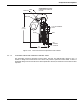
2-5 DIRECTIONAL (STOP) VALVES
Directional (stop) valves find two primary applications in carbon dioxide systems. The first
application is in multi-hazard systems which share a common carbon dioxide suppression
system. Directional valves are used to route the carbon dioxide from the shared supply to the
individual areas or equipment being protected.
The second application for these valves is as a life safety device to prevent the accidental
discharge of carbon dioxide into a normally-occupied area. The stop valve prevents the flow of
carbon dioxide until the attached control head is operated.
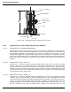
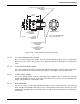
All Kidde Fire Systems directional (stop) valves operate on a differential-pressure principle,
utilizing the pressure of the discharging carbon dioxide to open the stop check and allow flow
through the valve. All valves automatically reset (close) after discharge is completed.
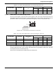
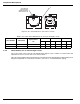
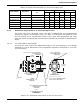
2-5.1 Directional (Stop) Valves (1/2-inch through 2-inch)
The 1/2-inch through 2-inch size directional valves (Figure 2-51) have bronze bodies which
house a stop check and an actuating piston, along with an external port for attachment of a
control head (part numbers and dimensions are provided in Table 2-20). Actuation of a control
head allows the discharged carbon dioxide to apply pressure to the actuating piston to open
the stop check.
These directional valves have threaded inlet and outlet ports for connection to the distribution
piping.
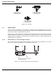
Figure 2-51. Directional (Stop) Valves (1/2-inch through 2-inch)
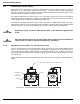
CAUTION
Directional (stop) valves do NOT prevent flow in the direction opposite the
arrow.
CAUTION
All control heads must be in the set position before attaching to the directional
(stop) valves, in order to prevent accidental CO
2
discharge.
B
C
A
INLETVALVE SIZE
OUTLET
NPT
BOTH ENDS
1-1/4 - 18 NF-3 FOR CONTROL HEAD CONNECTION