
User's Manual

Component Descriptions
P/N 81-CO2MAN-001 2-45 September 2013
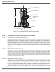
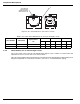
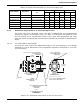
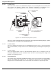
Figure 2-50. Check Valves (2 1/2-inch to 3-inch)
2-4.3.1 2 1/2-INCH WELDING NECK FLANGE
The 2 1/2-inch welding neck flange, Part No. WK-263716-000 (Figure 2-50), is required to
attach the 3-inch check valve to 2 1/2-inch distribution piping. Two flanges are required per
valve.
2-4.3.2 3-INCH WELDING NECK FLANGE
The 3-inch welding neck flange, Part No. WK-681012-000 (Figure 2-50), is required to attach
the 3-inch check valve to 3-inch distribution piping. Two flanges are required per valve.
2-4.3.3 3-INCH FLANGE GASKET
The 3-inch flange gasket, Part No. WK-200973-000 (Figure 2-50) is required to seal the
connection between the 3-inch check valve and either the 2 1/2-inch or 3-inch welding neck
flange. Two gaskets are required per valve.
2-4.3.4 NUTS AND BOLTS
3/4-inch hex nuts, Part No. WK-152308-000 (Figure 2-50), and 3/4-inch by 4 1/2-inch long
bolts, Part No. WK-196648-720 (Figure 2-50), are required to connect the 2 1/2-inch or 3-inch
welding neck flanges to the 3-inch check valve. A total of 16 nuts and bolts are required per
check valve.
INLET
3/4 in. X 4-1/2 in. (114 mm) LG. HEX BOLT
P/N WK-196648-720
16 REQUIRED
10-1/2 in.
(267 mm)
OUTLET
3/4 in. HEX NUT
P/N WK-152348-000
16 REQUIRED
GASKET
P/N WK-200973-000
2 REQUIRED
2-1/2 in. WELDING NECK FLANGE
P/N WK-263716-000
2 REQUIRED
-OR-
3 in. WELDING NECK FLANGE
P/N WK-681012-000
2 REQUIRED
SIDE VIEW
WITHOUT
ASSEMBLED FLANGE
8-1/4 in. (210 mm) DIAMETER FLANGE
6-5/8 in. (168 mm) BOLT CIRCLE