
User's Manual

Component Descriptions
P/N 81-CO2MAN-001 2-43 September 2013
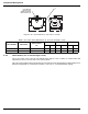
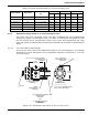
2-4.2 Check Valves (1/2-inch through 2-inch)
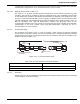
The 1/2-inch through 1 1/4-inch check valves (Figure 2-48) are in-line valves and consist of a
threaded brass body which houses a spring loaded piston; part numbers and dimensions are
provided in Table 2-18. The piston permits flow through the valve in one direction only.
Figure 2-48. Check Valves (1/2-inch to 1-1/4-inch)
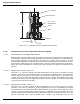
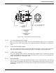
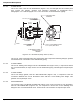
The 1-1/2-inch and 2-inch check valves (Figure 2-49) consist of a brass body which houses a
spring loaded stop check; part numbers and dimensions are provided in Table 2-19. The stop
check permits flow in one direction only.
These valves are fitted with threaded inlet and outlet ports.
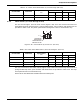
Table 2-17. Check Valve Dimensions (1/4-inch through 3/8-inch)
Part Number Valve Size
Pipe Thread
“C”
“A” “B”
in. mm in. mm
WK-264985-000 1/4 in. 1/4 in. - 18 NPT 2.00 51 0.81 21
WK-261193-000 3/8 in. 3/8 in. - 18 NPT 2.35 60 1.00 25
Table 2-18. Check Valve Dimensions (1/2-inch through 1-1/4-inch)
Part Number Valve Size
Pipe Thread
“C”
“A” “B”
in. mm in. mm
81-800327-000 1/2 in. 1/2 in. - 14 NPT 3.34 85 2 51
81-800266-000 3/4 in. 3/4 in. - 14 NPT 3.34 85 2 51
WK-800443-000 1 in. 1 in. - 11.5 NPT 3.97 101 3.18 81
81-800444-000 1-1/4 in. 1-1/4 in. - 11.5 NPT 3.97 101 3.18 81
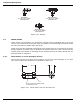
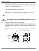
A
C
B
VALVE MUST BE
INSTALLED WITH
ARROW POINTING IN
DIRECTION OF FLOW