
User's Manual

Component Descriptions
September 2013 2-32 P/N 81-CO2MAN-001
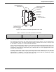
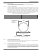
regular pneumatic control head except that its detection chamber has no vent. Thus, all the
compensation for normal environmental pressure changes is performed by the vented
pneumatic control head. The diaphragm pressure setting of the tandem control head is chosen
to match that of its corresponding vented pneumatic control head. The two diaphragm
chambers are interconnected via 3/16-inch copper tubing. If the system is to be actuated
remotely via a pull box and cable, the manual cable control is connected to both the pneumatic
and tandem control heads.
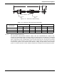
Figure 2-36. Tandem Pneumatic Control Head
2-3.6 Components for Pneumatic Actuation Systems
Pneumatic (rate-of-rise) systems utilize a variety of specialized components to control the
actuation of a carbon dioxide suppression system.
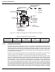
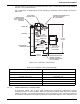
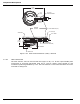
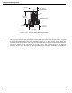
2-3.6.1 PNEUMATIC CABLE HOUSING
A pneumatic cable housing (Figure 2-37) is required when a pneumatic control head and a
tandem control head are installed for simultaneous actuation by a remote pull box and cable.
The housing protects the interconnecting cable between the two pneumatically-operated
control heads and to secure the heads in a fixed position. The length of the cable housing (see
Table 2-12) is determined by the size of the cylinders used in the suppression system.
16
1"
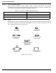
3/16 in. x 17 in. LONG
COPPER TUBING
P/N WK-802366-000
CABLE BLOCK
PRIMARY PNEUMATIC
CONTROL HEAD (VENTED)
CYLINDER CENTERS
CABLE HOUSING
TANDEM PNEUMATIC
CONTROL HEAD
3/8 in. PIPE OR
ALTERNATE ASSEMBLY
CABLE
3/16 in. COPPER TUBING
CONNECTION
3/16 in. TUBING TEE (SUPPLIED
WITH TANDEM CONTROL HEAD)