
User's Manual

Component Descriptions
P/N 81-CO2MAN-001 2-31 September 2013
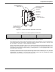
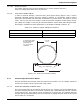
the vent setting, the smaller the actual size of the vent. A control head with a high setting is
actually a very sensitive device.
The combination of diaphragm and vent settings for pneumatic control heads are shown in
Table 2-11.
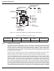
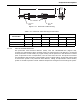
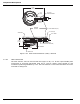
Figure 2-35. Pneumatic Control Head
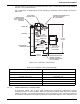
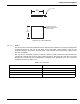
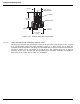
2-3.5.1 TANDEM PNEUMATIC CONTROL HEAD
As previously stated, two or more pilot cylinders are required for suppression systems
consisting of three or more cylinders. When two pneumatic control heads are used to actuate
a bank of cylinders, one control head must be of the type having a vent, and the second must
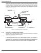
be a tandem control head. The tandem pneumatic control head (Figure 2-36) is identical to the
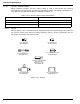
Table 2-11. Pneumatic Control Head Settings
Setting Control Head Part Number
3 inches, 5 sec. vent 81-872335-000
6 inches, 5 sec. vent 81-872365-000
6 inches, 2 sec. vent 81-872362-000
1 inch, Tandem 81-872310-000
3 inch, Tandem 81-872330-000
6 inch, Tandem 81-872360-000
PATENT: 246675
WALTER KIDDE
PART NO.
SET
RELEASED
INSTRUCTIONS
SEE
MAINTENANCE
FOR
USE SCREWDRIVER
PULL
CABLE
Kidde
TO RESET
CONTROL HEAD
PNEUMATIC
CONECTION FOR
DETECTION TUBING
3/16 in. TUBING NUT
FITS HERE
CONNECTION FOR REMOTE PULL
BOX PIPE OR CONDUIT
3/8 in. NPS FEMALE
LOCAL MANUAL
RELEASE LEVER
SWIVEL NUT
1-1/2 in. (38 mm)
HEX 1-1/4-18
NF-3 THREAD
4-13/16 in.
(122 mm)
CONNECTION FOR CABLE
HOUSING TO SECOND
CONTROL HEAD (IF USED)
3/8 in. NPS FEMALE
3-5/16 in.
(84 mm)
INDICATOR AND
RESET STEM
SEAL WIRE
LOCKING PIN