
User's Manual

Component Descriptions
September 2013 2-28 P/N 81-CO2MAN-001
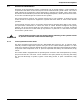
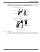
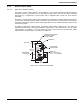
Figure 2-32. Electric Control Head (Cover Removed)
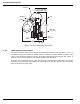
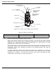
2-3.4.2 ELECTRIC AND CABLE-OPERATED CONTROL HEADS
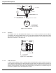
These control heads (Figure 2-33) provide for electric, local manual and remote manual
actuation of the CO
2
cylinder valve or directional (stop) valve. The control head is operated
electrically by a suppression control panel or mechanically by a cable pull box. it is also
equipped with a lever for local manual operation.
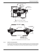
These heads contain a microswitch whose contacts are used to break the electrical circuit to
the solenoid when the head is actuated. This reduces the overall power consumption of the fire
suppression system. The actuating pin latches in the released position and must be
mechanically reset.
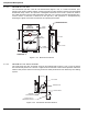
A suitable suppression control panel, specifically listed and/or approved for use with the
following control heads shall be provided for supervision of the releasing circuits per NFPA
requirements. In addition, a 24 hour back-up power source shall be provided per NFPA
requirements. Electrical data is contained in Table 2-9.
Table 2-8. Electric Control Head
Control Head Part Number Voltage Amps.
WK-890181-000 24 Vdc 2.0 momentary
3/4 in. NPT TO FLEXIBLE
CONDUIT ADAPTER
PLUS OR HOT CONNECTION
(TERMINAL #3)
TERMINAL STRIP
MICROSWITCH
MICROSWITCH LEVER
INDICATOR AND
RESET STEM
CAM
SWIVEL NUT
MINUS, NEUTRAL, OR
GROUND CONNECTION
(TERMINAL #1)
OPTIONAL CONNECTION
FOR MICROSWITCH
(TERMINAL #2)
FLEXIBLE
CONDUIT