
User's Manual


September 2013 B-10 P/N 81-CO2MAN-001
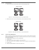
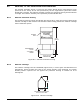
B-7.1.2 WIRING DIAGRAM
1. With the ball valve in the fully open position (normal operating mode).
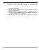
Figure B-7. Switch When Ball Valve is in Fully Open Position
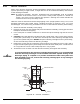
2. With the ball valve in the fully closed position (service/maintenance mode).
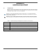
Figure B-8. Switch When Ball Valve is in Fully Closed Position
B-7.2 Lockout Valves Maintenance
When it is necessary to perform maintenance on the CO
2
system or need to perform work that
could cause false alarms and discharge, it is essential to lockout the CO
2
system. The following
steps must be observed.
1. Unlock the valve and place it in the Closed position.
2. Lock the valve.
3. Verify that a Trouble indicator appears on the control unit.
4. When maintenance or test is complete, unlock the valve and place it in the Open position.
5. Lock the valve.
6. Verify the Trouble indicator is clear on the control unit.
12 3
NC
C
NO
BLACK
RED
WHITE
4
5
6
NC
C
NO
BLACK
RED
WHITE
SWITCH 1 IS OPEN
SWITCH 2 IS CLOSED
SWITCH 1
SWITCH 2
12 3
NC
C
NO
BLACK
RED
WHITE
4
5
6
NC
C
NO
BLACK
RED
WHITE
SWITCH 1 IS
SWITCH 2 IS
CLOSED
OPEN
SWITCH 1
SWITCH 2