
User's Manual


September 2013 B-8 P/N 81-CO2MAN-001
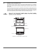
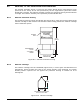
B-7 LOCKOUT VALVES
Figure B-6. CO
2
Lockout Valve with Limit Switch
A lockout valve is a manually operated valve installed between the carbon dioxide manifold and
the discharge pipe to the protected area. The lockout valve can be locked in the closed position
to prevent carbon dioxide from discharging into the protected area. The lockout valve shall be
installed at the end of the carbon dioxide manifold or, if a common manifold protects multiple
hazards, after each directional (stop) valve.
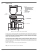
The lockout valve consists of a stainless steel ball valve with union ends. The ball valve has a
2,500 PSIG pressure rating. A NEMA4 enclosure, housing two SPDT limit switches with a 15A
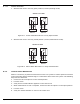
rating, sits atop the valve. Limit Switch No.2 shall be wired in series with the electric control
head in the releasing circuit. Limit Switch No.1 may be wired to provide positive indication that
the valve is fully closed.
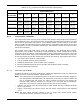
Table B-2 lists the lockout valve with limit switch specifications.
Note: The CO
2
Lockout Valve is not a UL listed item.
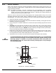
5-17/64 in.
(134 mm)
5-3/64 in.
(148 mm)
F
G
D
A
C
B
E
SWITCH
ENCLOSURE
LOCKING HASP
HANDLE (SHOWN IN
THE OPEN POSITION)
1. BALL VALVE:
PRESSURE RATING 2,500 PSIG (127 BAR)
DOUBLE UNION END WITH NPT FEMALE
PIPE CONNECTIONS LOCKING
HANDLE AND BRACKET FOR BOTH
OPEN (PARALLEL WITH VALVE BODY)
AND CLOSED (PERPENDICULAR TO
VALVE BODY).
2. LIMIT SWITCH:
TWO (2) SPDT SWITCHES
NEMA 4 ENCLOSURE
3. LOCK NOT INCLUDED