
User's Manual

P/N 81-CO2MAN-001 B-5 September 2013
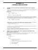
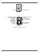
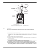
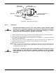
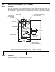
Figure B-3. Pneumatic Transmitter
B-4.2 Installation
1. Refer to Figure B-3 and remove protection cap from pilot control port of the stop valve.
2. Position pneumatic transmitter on stop valve pilot control port.
3. Run 3/16-inch copper tubing from the pneumatic transmitter to a junction box located
adjacent to the transmitter.
4. Using reducing union Part No. 81-802536-000, connect the 3/16-inch O.D. tubing to the
1/8-inch tubing going to the pneumatic control heads on the pilot cylinders.
5. Make electrical connections.
Note: When the pneumatic transmitter is installed on main and reserve systems and the
reserve system has not been previously discharged, reset the pneumatic transmitter on
the directional (stop) valve.
WARNING
Pneumatic transmitter must be in the “Set” position (green indicator visible
through slots in cap) before installing on the stop valve. Pneumatic transmitter
left in the “Actuated” position will allow inadvertent discharge of carbon
dioxide into the hazard if the CO
2
cylinders are actuated.
WARNING
Do not test or actuate the pneumatic transmitter with the pneumatic control
heads attached to the pilot CO
2
cylinders. Actuation of the pneumatic
transmitter will cause the control heads to operate and result in CO
2
system
discharge.
CONNECTION FOR 3/16 in.
COPPER TUBING
SWIVEL NUT
ACTUATION
SHAFT
RESET CAP
SWITCH-ONLY
ON P/N 890176
CONNECTION
FOR CONTROL HEAD
OPERATING
SHAFT
BELLOWS