
User's Manual

September 2013 B-4 P/N 81-CO2MAN-001
1. Remove funnel. Make certain the flat rubber gasket is in place at bottom of the vent port.
Install vent plug assembly. Tighten securely with Kidde Fire Systems tool Part No. 209145
while holding hex of vent housing with a wrench.
2. Keep mercury check upright at all times to prevent mercury from spilling out of wells.
3. Sequentially connect a manometer test set, Part No. 840041, to each well inlet using the
conversion coupling supplied with the test set to make connection. Close off tube “B”
(noted on manometer instructions) and gently squeeze the rubber bulb until a slight
pulsing is felt in the bulb. This can be visually observed as a dropping off of the reading,
followed by a steady reading as continued pressure is applied to the rubber bulb of
manometer. The sum of the readings of both legs of the manometer is the setting of the
well under test. The setting is obtained by turning the adjustment screw under each well
in either and upward or downward position. Turing the screw upward increases the setting;
turning the screw downward decreases the setting. Repeat this adjustment for each
additional well.
4. Attach the 1/8-inch tubing to a check union, as applicable, and secure in place using a
tubing nut.
5. Upon completion of the adjustments and assembly of the tubing to the unions, close the
box cover and assemble the seal wire. Crimp the lead seal with pliers or a crimping tool.
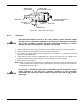
B-4 PNEUMATIC TRANSMITTER
B-4.1 Description
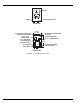
The pneumatic transmitter, Part No. 890176 (Figure B-3), is an intermediary actuation device
used for pneumatic systems that employ directional (stop) valves. It is always used in
conjunction with a pneumatic control head. The function of the pneumatic transmitter is to
engage the pilot check on the directional (stop) valve and to retransmit the pneumatic
actuation signal to the pilot cylinders controlling the discharge of the suppression system.
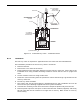
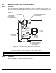
The pneumatic transmitter consists of a metal body to which a bellows housing is attached.
The body contains an actuator rod to engage the pilot check of a directional (or stop) valve and
a spring loaded bellows assembly located in the attached housing. The associated pneumatic
control head mounts to the pilot port on the body. Activation of the control head displaces the
actuator rod to open the pilot check on the directional valve and to release the spring loaded
bellows assembly. The compressed air is transmitted via copper tubing to the pilot CO
2
cylinders controlling the actuation of the suppression system. The pneumatic transmitter is
connected to the system's 1/8-inch copper tubing network via a short segment of 3/16-inch
tubing and has a normally open micro switch contact that closes upon actuation. A visual
indicator shows when the transmitter is in its set position. The pneumatic transmitter requires
manual reset after actuation.
WARNING
Wear rubber gloves when filling mercury wells. Flush gloves with water and
wash hands thoroughly after filling procedure has been completed. Avoid
touching hands to mouth or eyes. Contact a physician immediately if irritation
develops.