
User's Manual

Maintenance
September 2013 6-8 P/N 81-CO2MAN-001
6-5.4 Pneumatic Detection System Tests
6-5.4.1 PNEUMATIC CONTROL HEAD TEST - PRESSURE SETTING
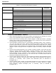
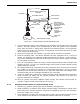
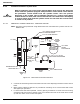
Note: The tests to be performed using Manometer Test Set Kidde Fire Systems Part No. 81-
840041-000.
Figure 6-3. Manometer Pneumatic Detection
1. Connect the test fitting of the manometer test set to the diaphragm chamber of the control
head.
2. Make certain sufficient clearance is provided at mounting nut so control head will not be
damaged upon operation.
3. If control head has been operated, reset by placing screwdriver in reset stem and turning
clockwise until stem locks in position. This occurs when the arrow on the reset stem is lined
up with the “SET” arrow on the nameplate.
CAUTION
Before conducting any of the tests outlined below first remove the discharge
heads from the cylinders equipped with pneumatic control heads. Then remove
the pneumatic control heads from the cylinder valves. This will prevent
discharge of the system upon accidental operation of a control head. When
tandem heads are used, back-off each head at the same time before attempting
to remove either head from the cylinder valves. Do not allow the control heads
to rotate out of position.
5
4
3
2
1
2
0
1
2
3
4
5
FILL HERE
MANOMETER TEST SET
P/N WK-840041-000
RUBBER
BULB
C
PNEUMATIC
CONTROL
HEAD
1/8 in. NUT P/N WK-207648-000
1/8 in. TUBING-FLARE END WITH NUT-
CUT OTHER END SQUARE
3/16 in. FEMALE FITTING
3/16 in. X 17 in. (432 mm)
LONG TUBING P/N WK-802366000
3/16 in. - 1/8 in.
UNION
P/N 81-802536-000
(REMOVE 1/8 in.
NUT)
RUBBER
TUBE
B
RUBBER
TUBE
A
1/8 in.
UNION
1/8 in.
NUT
SYSTEM
ACTUATION
TUBING
INDUSTRIAL
DETECTOR P/N
WK-840845-000
1/8 in. UNION
AND NUT
P/N 81-802535-000
FILL
TO
HERE