
User's Manual

Operation
P/N 81-CO2MAN-001 5-5 September 2013
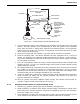
5-6 MAIN AND RESERVE SYSTEMS
After operating the “main” system as described above, place the “reserve” system in standby
mode as follows:
1. Reset all manually operated control heads, pressure operated trips, discharge indicators,
manual operation stations, and pressure operated switches. Ensure that the control panel
and all detectors are reset.
2. Ensure that the manual lever on the pneumatic Discharge delay is in the “closed” position
with the locking pin and seal wire installed.
3. If the system uses stop (directional) valves, reset control head on the valve.
4. Proceed to the main/reserve transfer switch. Move switch lever to the RESERVE position.
5. Immediately contact a Kidde Fire Systems distributor for service.
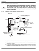
5-7 LOCKOUT VALVES
When it is necessary to perform maintenance on the CO
2
system or need to perform work that
could cause false alarms and discharge, it is essential to lockout the CO
2
system. The following
steps must be observed.
1. Unlock the valve and place it in the Closed position.
2. Lock the valve.
3. Verify that a Trouble indicator appears on the control unit.
4. When maintenance or test is complete, unlock the valve and place it in the Open position.
5. Lock the valve.
6. Verify the Trouble indicator is clear on the control unit.
WARNING
The following procedures can be applied only when the reserve system has not
been previously discharged.
WARNING
When pneumatic main/reserve transfer switch, Part No. 81-871364-000, is
installed, wait at least 15 minutes before moving lever to the “reserve”
position. This allows any remaining pressure in the pneumatic system to vent
to atmosphere. Failure to follow these instructions may accidentally discharge
the reserve system when the transfer switch is moved.