
User's Manual

Installation
P/N 81-CO2MAN-001 4-51 September 2013
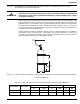
4-5.5 Safety Outlet
NFPA 12 requires a pressure relief device to be installed in sections of closed piping. These
"closed sections of pipe" are normally located between the carbon dioxide cylinders and
Directional (Stop) Valves or lock-out valves. In order to prevent over pressurization of this
closed section of pipe when carbon dioxide is trapped and in the event of high temperature
exposure, a pressure relief device (Safety Outlet) is required.
1. Locate the Safety Outlet in an area where the carbon dioxide can be safely discharged
without exposing personnel.
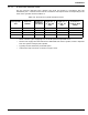
2. Ensure that the maximum allowable working pressure of the closed section of pipe is equal
to or greater than the maximum operating pressure of the Safety Outlet, which is 2,800
psig for part number 81-803242-000.
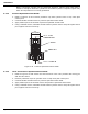
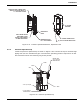
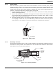
3. The Safety Outlet (Figure 4-41) must be installed upstream of any stop valve. Connection
to the piping is made with a 3/4-inch NPT fitting. Attach the wrench to the body of the
safety outlet. Do not tighten or loosen the retaining nut containing the safety disc.
Figure 4-41. Safety Outlet
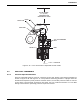
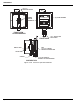
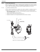
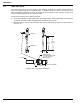
4-5.6 Discharge Indicator
The discharge indicator (Figure 4-42) must be installed on the discharge manifold in either a
horizontal or vertical position. The indicator has a 3/4-inch NPT male connection. Make certain
the indicator stem is in the normal position.
Figure 4-42. Discharge indicator
SEAL WIRE
BODY
3/4 in. NPT MALE
RETAINING NUT
BODY
3/4 in. NPT MALE
1-1/8 in. (29 mm) HEX
ACROSS FLATS
STEM
CAP
NORMAL
POSITION
DISCHARGE
INDICATION
POSITION