
User's Manual

Installation
September 2013 4-50 P/N 81-CO2MAN-001
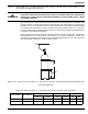
4-5.4 Odorizer
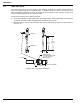
When used, odorizer assemblies should be located immediately downstream of each selector
valve. For systems protecting a single hazard, a single odorizer assemble can be located
immediately downstream of the discharge manifold.
The odorizer assembly shall be installed upstream of the lock-out valve. In the event a safety
outlet ruptures in a locked-out system, the scent from the odorizer will provide a warning that
carbon dioxide has vented into the area by the safety outlet.
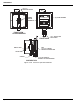
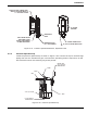
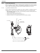
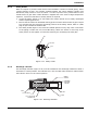
Odorizer assemblies must be attached to the discharge piping in the upright position. The
odorizer assembly requires approximately 9” of clearance. Odorizer assemblies connect to a
3/4” NPT fitting.
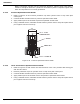
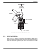
1. Install the 3/4” NPT fitting where the odorizer assembly will be located.
2. Screw the odorizer assembly to the 3/4” NPT fitting.
Figure 4-40. Odorizer Installation
CAUTION
To prevent damaging the odorizer assembly during testing, it is recommended
that the odorizer assembly not be installed until after system testing of the
discharge piping is complete. For periodic maintenance after the system has
been installed and in use, remove the odorizer assembly prior to any testing of
the discharge piping.
8.7” REF