
User's Manual

Installation
September 2013 4-42 P/N 81-CO2MAN-001
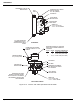
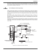
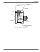
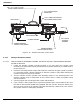
Figure 4-32. Tandem Pneumatic Control Head
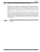
4-4.11 Nitrogen Actuation Station
4-4.11.1 INSTALLATION OF NITROGEN CYLINDER, P/N WK-877940-000, AND MOUNTING BRACKET,
P/N WK-877845-000
1. Locate the nitrogen cylinder mounting bracket in an area where the cylinder valve
assembly and control head will be protected from inclement weather by a suitable total or
partial enclosure.
2. Install the mounting bracket clamps and hardware. Install the nitrogen cylinder in position
in a mounting bracket; tighten sufficiently to hold the cylinder in place while allowing the
cylinder enough free play to be rotated.
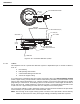
3. Turn the cylinder until the cylinder valve discharge outlet is in the desired position. The
nitrogen cylinder must be positioned so that control head is readily accessible during
manual operation.
4. Securely tighten the mounting bracket clamps and hardware.
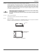
5. If the cylinder is being used to drive a pressure operated siren, P/N 90-981574-001, then
the add-on label P/N 06-231866-518 (supplied with the cylinder) should be affixed over
the area at the center of the cylinder main label (bounded by a dotted line). This ensures
the cylinder function is adequately indicated.
16
1"
3/16 in. X 17 in (432 mm) LONG
COPPER TUBING P/N 802366
CABLE BLOCK
3/16 in. COPPER TUBING
CONNECTION
3/16 in. TUBING TEE (SUPPLIED)
WITH TANDEM CONTROL HEAD
CABLE
3/8 in. PIPE OR
ALTERNATE
ASSEMBLY
TANDEM PNEUMATIC
CONTROL HEAD (NO VENT)
PRIMARY PNEUMATIC
CONTROL HEAD (VENTED)
CABLE HOUSING
CYLINDER CENTERS