
User's Manual

Installation
P/N 81-CO2MAN-001 4-39 September 2013
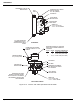
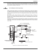
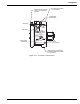
4-4.9.4.1 To Test Pneumatic Detectors And/or System Tubing For Tightness
Connect manometer system tubing as shown on Figure 4-29. Squeeze rubber bulb "C", then
close off rubber tube "A". Allowing rubber bulb "C" to expand gradually will cause water level
in manometer to change, and then hold steady. If detector(s) and/or system tubing is tight,
water level will not drop when observed for at least one minute. Relieve vacuum by opening
rubber tube "A". Hold a minimum of 8 inches vacuum (difference between 2 sides of "U" tube,
or 4 inches on each side of "U" tube).
4-4.9.4.2 Other Use For Manometer
Test tubing for freedom from obstructions before installation.
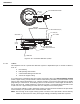
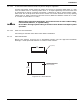
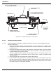
4-4.9.5 HEAT COLLECTOR
Mount heat collector (Figure 4-30) in designated location (see the approved installation
drawings). Install pneumatic detector in center of heat collector.
Figure 4-30. Heat Collector
CAUTION
When making tests with manometer, do not allow water to enter rubber tubing,
control head, detector, or system tubing.
Do not blow through system tubing as moisture from breath will impair system
operation.
16 in.
(406 mm)
1 in.
(25 mm)
MOUNTING SURFACE FOR
PNEUMATIC HEAT DETECTOR
(MOUNT IN CENTER)
16 in.
(406 mm)