
User's Manual

Installation
September 2013 4-38 P/N 81-CO2MAN-001
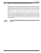
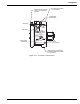
4-4.9.3 MANOMETER TEST PROCEDURE
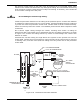
Fill manometer glass tube at point marked “FILL HERE” (see Figure 4-29). "Rock" water level
back and forth by squeezing rubber bulb to eliminate air bubbles. Add or pour out water until
level is at fill point marked “FILL TO HERE” (see Figure 4-29).
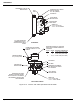
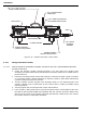
1. Connect the test fitting of the manometer test set to the diaphragm chamber of the control
head.
2. Make certain sufficient clearance is provided at swivel mounting nut so control head will
not be damaged upon operation.
3. If control head has been operated, reset by placing screwdriver in reset stem and turning
clockwise until stem locks in position (with arrow on reset stem lined up with "Set" arrow
on nameplate).
Note: Slight resistance will be met just before stem locks.
4. Close off the rubber tube "A" by squeezing tightly with the fingers or use a crimp clamp
and then apply pressure by gradually squeezing the rubber bulb "C". The control head
should operate at the factory pressure setting the 10% tolerance allowed. The pressure
required to operate the control head is the difference, in inches on the manometer,
between the water levels in the two tubes, and is equal to twice the reading of either tube,
for example, 3 inches both tubes or 1-1/2 inches one tube.
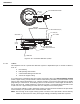
4-4.9.4 CONTROL HEAD VENT TEST
Before disconnecting the manometer from the control head, the vent must be tested. To test
the vent for correct calibration, perform the following:
1. Squeeze rubber bulb "C" about halfway or enough to achieve sufficient vacuum for test,
then close tube "A" by pinching with fingers or crimp clamp.
2. Let bulb expand gradually to its normal shape. This creates a partial vacuum, causing the
water level to change, indicating inches of vacuum applied to the control head (the vacuum
must be more than minimum of 3 inches in order to observe drop from 3 inches to 1 inch).
3. The water column will recede to "0" level as air passes through the vent. The time required
(number of seconds) for the water column to recede 2 inches reading from 3 inches to 1
inch on both legs or 1-1/2 inches to 1/2 inch on either leg is the number of the vent (the
calibrated rate of flow). For example, if the time required to pass the above amount of
water is 5 seconds the control head vent is "No. 5". When vents are tested in control heads,
the time will vary due to the control head diaphragm volume and a No. 5 vent will test 5-
7 seconds, which is acceptable. If a vent reads much higher, it will increase system
sensitivity; if a vent reads much lower, it will decrease system sensitivity and may not be
acceptable.
4. Repeat above procedure for testing tandem control head (if installed). Since there is no
vent in the tandem control head, the vacuum should hold (same as tubing tightness test).
5. Disconnect manometer test set from the control head (test fitting "A"). Reset the control
head by turning the reset stem to its "SET" position.
CAUTION
After the control head has operated, be sure to release rubber tube "A" first
before allowing the rubber bulb "C" to expand to normal; otherwise water may
be sucked into the tubing and control head, causing serious problems.