
User's Manual

Installation
P/N 81-CO2MAN-001 4-31 September 2013
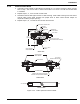
4-4.6 Tandem Control Head
1. Install first control head as described in Paragraph 4-4.3, steps 1 through 7 above, except
that in step 7 the closure disk is omitted and cable is not to be cut until the second head
is installed.
2. Repeat steps 1, 2, 3 for second control head.
3. Assemble second cable pipe locknut to cable housing. Slide cable housing over free end of
control cable. Place cable housing into proper slots in both control heads. Adjust as
required to obtain proper spacing.
4. Repeat steps 5, 6, 7 and 8 for the second control head.
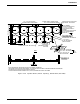
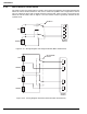
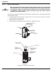
Figure 4-25. Cable Operated Control Heads
SINGLE HEAD
TANDEM HEADS
CABLE HOUSING
LOCAL MANUAL RELEASE LEVER
SEAL WIRE
LOCKING PIN
DIRECTION OF
PULL
THREADED NUT
3/8 in. NPS FOR PIPE
1/16 in. CABLE
3/8in. PIPE (or 1/2 in. EMT
WITH ADAPTER P/N WK--843837-000)
SWIVEL NUT
1-1/2 in.
(38 mm)
1-1/4 in. - 18 NF-3
FEMALE
CLOSURE
DISC
4-1/4 in.
(108 mm)
CABLE CLAMP AND
WHEEL ASSEMBLY
CABLE CLAMP AND
WHEEL ASSEMBLY
CABLE HOUSING
3/8 in. PIPE OR
ADAPTER P/N WK-843837-000
1/16 in. CABLE
CYLINDER CENTERS
FLARE ON CABLE HOUSING FITS INTO SLOT
IN CONTROL HEAD (CLOSURE DISC REMOVED)
3/8 in. NPS MALE
FLARED