
User's Manual

Installation
P/N 81-CO2MAN-001 4-27 September 2013
a. Any bypass of the discharge delay must be supervised.
b. The discharge delay may be installed in the discharge piping or the actuation line.
Note: The discharge delay period is preset at the factory; however, the actual discharge delay
period may vary up to 100% depending on the ambient conditions and/or variations in
installation.
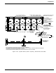
4-3.12 Discharge Nozzles
After the system piping has been blown free of debris, install the discharge nozzles in strict
accordance with the approved installation drawings and acceptable engineering practices.
Make certain the correct nozzle type, part number, and orifice size are installed in the proper
locations. Ensure that the nozzles are securely tightened to the piping.
4-4 ACTUATION SYSTEMS
4-4.1 Lever Operated Control Head
Install the lever operated control head by following the steps listed below:
1. Inspect the threads and control head for damage. Ensure the locking pin and seal wire are
intact.
2. Remove the protection cap from the appropriate control port.
3. Using a suitable wrench, tighten the swivel nut securely to the control port.
4. Provide suitable clearance around the control head to allow operation.
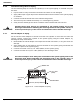
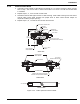
4-4.2 Cable Operated Actuation System Components
Kidde CO
2
cable operated devices must use 1/16-inch stainless steel cable run in 3/8-inch NPT
galvanized pipe or 1/2-inch conduit. Do not run more than one cable in each pipe/conduit run.
At each change in direction, use either the 3/8-inch NPT corner pulley or the 1/2-inch EMT
corner pulley for conduit as required. Do not bend the pipe or conduit.
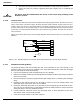
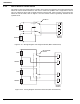
To install a cable operated control system, affix the pull boxes to an appropriate structure at
the locations noted on the installation plan. Connect the pipe/conduit to the pull boxes and
install the necessary pipe/conduit sections, corner pulleys and cable devices (i.e., dual pull
mechanism, tee pulley, dual pull equalizer, etc.) to terminate at the cable operated control
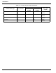
head(s). Do not exceed the allowable corner pulley quantities and cable lengths as noted in
Table 4-4. Remove all the corner pulley covers. Run the cable from the pull boxes through the
pipe/conduit, corner pulleys and other cable devices. Reattach the corner pulley covers.
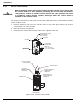
After completing the cabling, test each pull box for pull length and pull force. Ensure the cable
controls do not require more than 40 lb. (178 N) and 14 inches (356 mm) of pull length.
The following sections will detail the specific installation requirements for all the components
necessary to complete the cabling.